Frontier Technology Portal Independent technology analysis / Updated daily
Frontier Technology Portal logo
FRONTIER Technology Portal for the next wave of invention

Category: Clean Energy

Solar, batteries, grids, hydrogen, nuclear, storage, materials, and energy software.

  • How Agrivoltaics Changes the Design of a Solar Farm

    How Agrivoltaics Changes the Design of a Solar Farm

    A conventional solar farm is designed to turn available sunlight into electricity. An agrivoltaic farm has a second job: leave enough light, space, and access for agriculture to remain productive. The same panels that generate power change the field beneath them, altering shade, moisture, and the routes available to machinery. Success therefore depends on designing an agricultural system and an energy system together.

    That makes agrivoltaics an interesting clean-energy technology, but not a universal solution to competition for land. It can make some sites more useful, while a poorly matched crop and panel layout can undermine the farming activity it was meant to preserve. The question is not whether plants can grow beneath panels. It is whether a particular combination produces worthwhile food and electricity over many seasons.

    Agrivoltaics describes several different arrangements

    The US Department of Energy’s overview describes agrivoltaics, or dual-use solar, as agriculture beneath or between photovoltaic panels, including crops, livestock grazing, and pollinator habitat. Those uses have different design requirements. A sheep-grazing site is not the same agricultural proposition as a vegetable farm or an apple orchard.

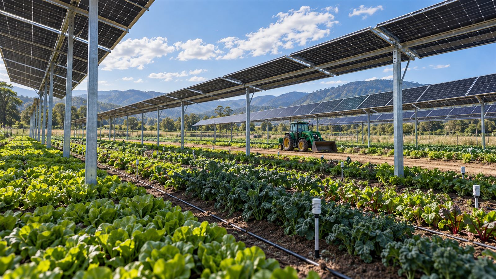
    Crop-based systems may raise modules overhead, leave wide spaces between rows, or arrange panels so agricultural equipment can operate between them. A useful project description should identify the actual activity, how much usable area remains, and who performs the agricultural work. A photograph of greenery alone cannot establish that commercial farming continues.

    Shade can help a crop and still reduce its harvest

    Panels intercept light that would otherwise reach plants. Partial shade can reduce heat and water stress, but plants also need light to produce the material that becomes a harvest. The balance depends on crop, climate, season, panel density, and irrigation. A cooler field is not automatically a more productive one.

    A 2025 field study of zucchini in a hot, semi-arid climate makes that distinction concrete. Under a high-density agrivoltaic array, researchers observed improved moisture conditions and some measures of plant physiological performance, but fruit yield was consistently lower than in the full-sun control. The findings concern that crop and experimental setup; they are neither proof that agrivoltaics always reduces yield nor a reason to assume water savings guarantee more produce.

    For a fruit-producing crop, a healthy-looking canopy is not enough. Researchers need to measure marketable output, quality, and the timing of harvest, alongside water use and electricity generation. The best shade pattern may change during a crop’s growth cycle, which makes crop-specific design more informative than a single annual average for sunlight.

    Panel height and spacing are engineering decisions

    Raising panels can make room for workers and machinery, but it changes the supporting structure. The DOE Farmer’s Guide to Going Solar notes that taller installations can need more steel and deeper supports because of wind loading. Wider panel and row spacing gives crops more light and equipment more access, while reducing the electricity that can be generated on the same land area.

    A workable layout must also account for turning space, irrigation lines, drainage, maintenance access, and electrical equipment. Construction that compacts soil or blocks a familiar field route can create agricultural costs after the solar array is already operating. These are design questions to settle with farmers early, rather than inconveniences to solve after installation.

    Module efficiency is still important, but improving the cell does not decide the field layout. The durability challenges discussed in our guide to tandem solar-cell reliability remain separate from whether a farm can grow and harvest crops efficiently around a long-lived array.

    Orchards offer a different design opportunity

    Some farms already install structures to protect crops from weather. That creates a different starting point from an open field. Fraunhofer ISE’s APV-Obstbau apple-orchard project investigates whether photovoltaic canopies can replace conventional protective structures while producing electricity and maintaining reliable, high-quality fruit production.

    The project compares agricultural protection and panel-design variants rather than treating all overhead coverage as equivalent. Its documented practical lessons include soil compaction during construction and the location of rainwater dripping from module edges. These details show why rainfall distribution and vehicle lanes belong in the solar design. The project is an example of a crop-specific research approach, not a guarantee that a photovoltaic roof will suit every orchard.

    Count both outputs without hiding the trade-offs

    An agrivoltaic site can be evaluated against two reference systems: comparable farming without panels and a solar installation without the agricultural constraints. A combined land-use measure can be helpful, but the underlying food and electricity figures should remain visible. Otherwise, a strong combined headline can obscure a meaningful loss in either output.

    A fair comparison also needs matching weather, crop varieties, irrigation practices, and measurement periods. One hot season may favor shade differently from a cool, cloudy season. Record marketable crop output, water use, labor, electricity delivered, and usable land area separately. These are evaluation questions, not performance results from a farm we have tested.

    Farm economics and the electricity grid still matter

    Sharing land does not automatically align the interests of a landowner, tenant farmer, and solar operator. Someone must maintain the crop activity, pay for additional structures, coordinate harvest and electrical maintenance, and manage the site over the project’s lifetime. Revenue from electricity does not reveal whether farming itself remains viable. A useful assessment makes those responsibilities explicit.

    The National Laboratory of the Rockies’ agrivoltaics program emphasizes collaboration among farmers, developers, and communities, alongside field research and analysis. That is important because a technically workable panel layout may still be a poor fit for local agricultural practices or community priorities.

    Grid access is another independent constraint. A dual-use field still needs somewhere to send electricity, or a suitable on-site load. Our explanation of clean-energy interconnection queues covers why a promising generation site can face connection delays. If a proposal includes irrigation or refrigeration as flexible loads, coordination with generation is a separate control problem, related to the principles behind virtual power plants.

    The evidence is growing, but it remains uneven

    A 2025 review of agrivoltaics research found substantial attention to crops, microclimates, and photovoltaic performance, with gaps in areas such as wildlife, policy, human health, and standardized methods. It also identified uneven geographic and topical coverage. Results from one research plot should therefore be transferred cautiously to another climate or farming system.

    We have not visited or tested the projects discussed here. The sources support the design trade-offs and reported research findings, not a prediction about a specific farm’s profitability. Local crop trials, operational evidence, and planning requirements remain important before treating a design as commercially proven.

    What to watch next

    Watch for multi-season trials that report crop quality, machinery access, water use, and delivered electricity together. Comparable control plots and transparent panel layouts would make results more useful than a headline about one unusually successful harvest. Practical reports should also show maintenance work, agricultural labor, and how responsibilities are divided.

    The most convincing agrivoltaic projects will make farming requirements visible in the engineering, from the choice of crop to the position of each support and drainage edge. Sharing a field can be valuable, but the value comes from a well-matched working system, not simply from putting solar panels above something green.

    Primary and authoritative sources

    Featured image is an AI-generated editorial illustration, not a photograph of a particular farm or research installation.
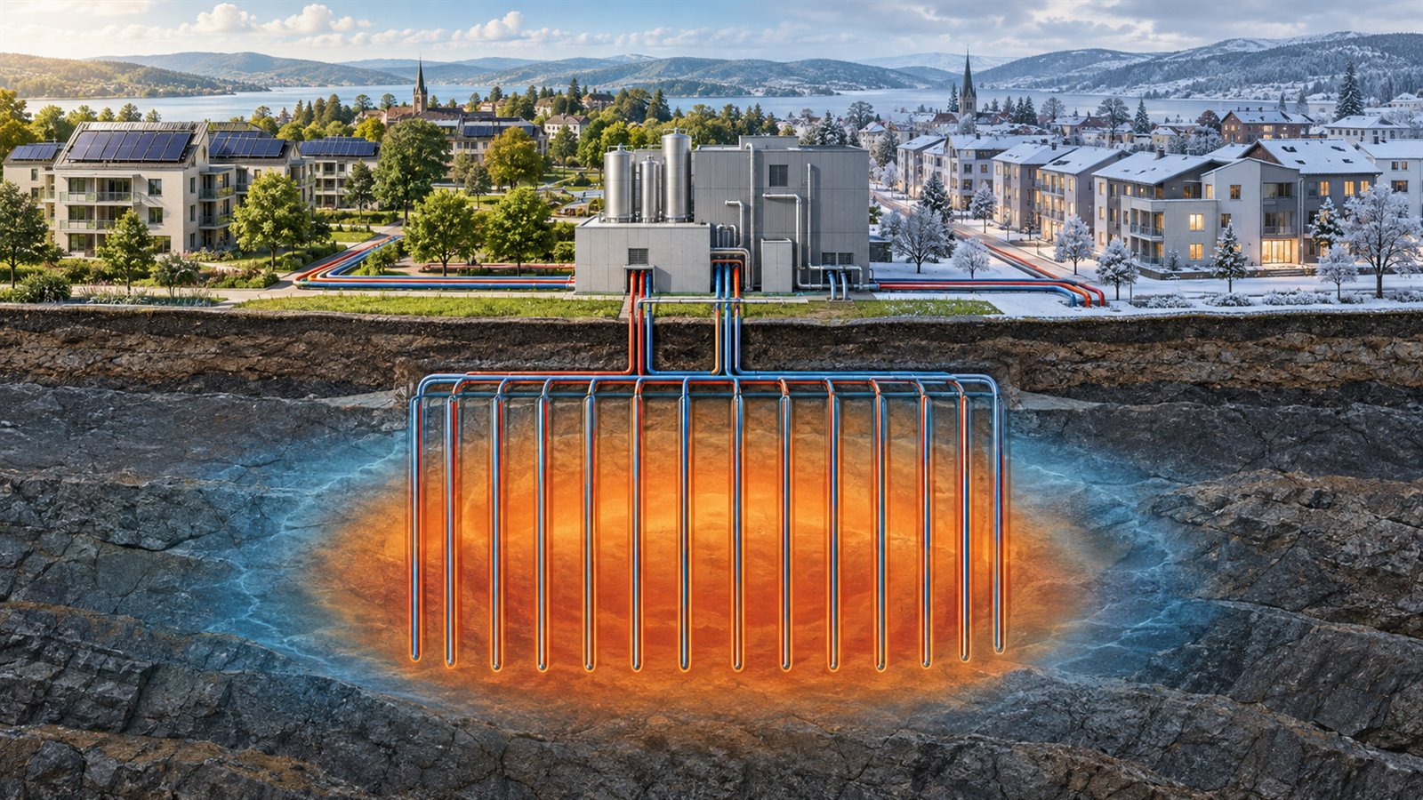
  • Seasonal Thermal Storage Is a Heat Bank, Not a Giant Battery

    Seasonal Thermal Storage Is a Heat Bank, Not a Giant Battery

    Clean heating has a timing problem. Solar heat is abundant in summer, electricity can be cheapest when wind and solar output is high, and industrial facilities often reject useful heat when nearby buildings do not need it. Winter demand arrives months later. A battery can shift electricity by hours, but storing heat directly can be a better match when the final service is warm water, space heating, cooling, or an industrial process.

    Seasonal thermal energy storage is the broad idea of banking heat or cold for weeks or months. It can use water, rock, soil, aquifers, phase-change materials, or reversible chemical reactions. The important point is that it is a thermal system, not simply a very large electrical battery. Its value depends on temperature, geology, heat pumps, distribution networks, and the customers that can use the recovered energy.

    Store the service instead of converting it twice

    Electricity is a flexible, high-quality form of energy. Turning it into heat is easy; turning low-temperature heat back into electricity is difficult and usually inefficient. If the customer ultimately needs heat, storing heat avoids an unnecessary round trip through electricity generation.

    The U.S. Department of Energy defines thermal energy storage as keeping energy in a material as a heat source or cold sink for later use. In buildings, it can shift heating or cooling demand away from expensive or grid-constrained hours. Over longer periods, the same principle can move summer heat into winter or winter cold into summer.

    This does not make thermal storage universally better than batteries. Electricity storage can serve motors, lights, electronics, and the grid directly. Thermal storage is strongest when a large, predictable thermal load exists close to the store.

    Duration changes the engineering

    A hot-water tank can shift demand within a day. Ice storage can make cold at night and use it during an afternoon cooling peak. Seasonal storage has a harder job: it must hold a much larger amount of energy while limiting losses over months.

    That changes the preferred shape and scale. Heat loss is related to surface area, while stored energy grows with volume. Large stores can therefore retain heat proportionally better than many small ones. District-scale pits, aquifers, and borehole fields can take advantage of this geometry, but they require land, drilling, civil works, and long-term planning.

    Our guide to long-duration energy storage makes the same broader point: duration is not a cosmetic specification. It changes which technology, business model, and end use make sense.

    Underground storage is several different technologies

    The Department of Energy’s geothermal energy storage overview separates three important underground approaches. Aquifer thermal energy storage, or ATES, circulates groundwater through permeable formations. Borehole thermal energy storage, or BTES, uses closed loops in drilled boreholes and does not depend on moving groundwater through the system. Reservoir thermal energy storage, or RTES, targets deeper formations and higher-temperature applications.

    Above-ground options are equally varied. Insulated water tanks and lined pit stores hold sensible heat, meaning their temperature changes as they charge and discharge. Phase-change materials absorb or release energy as they melt and solidify. Thermochemical systems store energy in reversible reactions and may offer higher energy density or low standing losses, but many are less mature.

    The DOE’s Thermal Energy Storage Technology Strategy Assessment describes this portfolio rather than one winning design. Water and ice are established; advanced phase-change and thermochemical materials still face questions around cost, cycling, containment, and system integration.

    Heat pumps make stored temperatures more useful

    A seasonal store does not always need to emerge at the exact delivery temperature. A heat pump can raise the recovered heat to the level required by a building or network. The warmer and more stable source can also help the heat pump operate more effectively than it would against very cold outdoor air.

    That relationship makes charging temperature, discharge temperature, and heat-pump performance part of one design. Storing heat at a higher temperature can increase losses and demand more expensive materials. Storing it cooler may preserve energy but require more electricity during discharge. Engineers must optimize the whole annual cycle, not one impressive temperature number.

    The same system logic applies to industrial heat pumps: a machine’s maximum outlet temperature says little without the source temperature, required lift, operating hours, and process integration.

    District energy creates the missing network

    Large seasonal stores need enough connected demand to justify their size. District heating and cooling networks provide that aggregation. The International Energy Agency’s 2026 report Renewables in District Energy says such networks already serve around 600 million people, while many systems still depend heavily on fossil fuels. It identifies geothermal, solar thermal, recovered heat, large heat pumps, and thermal storage as routes to cleaner operation.

    A network can collect heat from sources that would be too intermittent or dispersed for a single building. Data centers, wastewater, industrial processes, solar collectors, and electric heat pumps can charge shared storage. The store can then reduce peak boiler use and allow heat production to run when energy is available rather than exactly when customers open a tap.

    Thermal storage can help the electricity grid indirectly

    When a heat pump or electric boiler charges storage during periods of abundant electricity, the heating system becomes a flexible load. It can reduce consumption during a grid peak without making buildings cold because the thermal store continues supplying the network.

    This resembles a virtual power plant, but the controllable asset is heat production and storage rather than only an electrical battery. The European Commission’s Joint Research Centre notes in its thermal storage technology assessment that power-to-heat plus storage can decouple electricity consumption from immediate heating demand and support more variable renewable generation.

    The benefit is conditional. A store cannot respond faster than its pumps, controls, network, and customer constraints allow. Grid services also require metering, communications, market access, and a baseline against which flexibility can be measured.

    Efficiency is an annual system result

    Thermal stores are sometimes described with a single round-trip efficiency, but that number can hide important boundaries. Does it include pumping electricity, heat-pump input, distribution losses, auxiliary boilers, and heat remaining in the ground at season’s end? Is the recovered heat at a useful temperature?

    A fair comparison tracks delivered heat across an annual cycle. It should include standing losses, charge and discharge temperatures, flow rates, heat-pump coefficient of performance, network return temperature, and parasitic electricity. Exergy, a measure of how useful energy is at a given temperature, also matters: very hot energy is wasted if the customer only needs lukewarm water.

    Geology and permits can decide the project

    ATES needs a suitable aquifer and careful groundwater management. BTES avoids open groundwater circulation but requires enough drillable land and acceptable spacing between boreholes. Deeper reservoir systems add subsurface uncertainty, well cost, and monitoring requirements. Pit storage needs a large excavation, durable liners, insulation, and water management.

    Projects must consider thermal movement beyond the property, groundwater protection, existing wells, underground utilities, and the possibility that neighboring systems interfere with one another. Early site characterization is not paperwork added after the technology choice; it determines which technology is possible.

    Limitations and what to watch next

    Seasonal thermal storage is infrastructure-heavy and location-specific. It works best with dense, durable heat demand and a network that can accept lower temperatures. Retrofitting old steam systems, financing drilling, coordinating many building owners, and assigning subsurface rights can be harder than the storage physics.

    Watch for better field data on multi-year thermal recovery, wider use of low-temperature district networks, and validated thermochemical systems that retain energy with smaller standing losses. Also watch for projects that combine cooling, heating, and grid flexibility rather than valuing each service separately. The winning designs will be measured by reliable heat delivered over years, not by storage capacity alone.

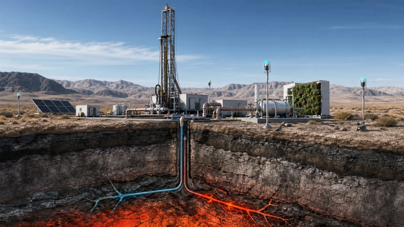
    Featured image: AI-generated editorial illustration of a district energy system and borehole thermal store. It does not depict a specific project or hands-on test.

    Primary and authoritative sources

  • A Fusion Power Plant Must Manufacture Its Own Fuel

    A Fusion Power Plant Must Manufacture Its Own Fuel

    Fusion headlines usually focus on plasma temperature, confinement, or experimental energy records. A commercial power plant would face another decisive test: keeping itself supplied with tritium. The favored deuterium-tritium reaction consumes a hydrogen isotope that is scarce, radioactive, and unavailable as an ordinary industrial fuel. A viable plant must manufacture new tritium from lithium, recover unused fuel, and return it to the reactor through a controlled closed cycle.

    This makes the inner wall far more than protective armor. Its breeding blanket would be a fuel factory, heat exchanger, radiation shield, and maintainable nuclear component at once. Making those functions work together will help determine whether fusion moves from impressive experiments to repeatable electricity production.

    Why deuterium-tritium fusion gets the attention

    Most near-term fusion concepts concentrate on deuterium and tritium because their reaction is comparatively achievable with modern plasma systems. Fusion produces a helium nucleus and a high-energy neutron. The helium can help heat the plasma, while the neutron escapes the magnetic field and deposits its energy in surrounding structures.

    Deuterium can be obtained from water, but tritium is a different proposition. It has a half-life of about 12.3 years, so any inventory naturally declines over time. According to ITER’s explanation of tritium breeding, future fusion plants will need to breed the fuel they consume rather than rely on the limited external supply. A physics result can demonstrate that fusion reactions occurred; it does not demonstrate that a power station can sustain its own fuel inventory.

    The blanket becomes a fuel factory

    The basic idea uses the neutron from the fusion reaction. A blanket containing lithium surrounds much of the plasma chamber. When neutrons interact with lithium, nuclear reactions can create tritium. The newly produced tritium then has to be removed from the blanket material, purified, measured, stored, and eventually delivered back to the plasma.

    The International Atomic Energy Agency describes three central blanket jobs: breeding tritium, extracting useful heat, and shielding components from fusion neutrons. Those jobs compete for space and materials. More structural metal can improve strength but absorb neutrons that might otherwise help breed fuel. More coolant hardware can improve heat removal while complicating geometry, maintenance, and tritium extraction. Designers may also add neutron-multiplying materials, such as beryllium or lead, to improve the neutron economy.

    Blanket concepts differ substantially. Some use lithium-containing ceramic pebbles with helium cooling. Others use liquid lithium-lead mixtures as breeder and coolant, or pair the liquid metal with a separate coolant. Tradeoffs include corrosion, pumping, magnetic effects, temperature limits, tritium retention, and remote maintenance.

    One neutron does not guarantee one usable tritium atom

    A simple diagram can make breeding look automatic, but a real plant loses neutrons and tritium at many points. Neutrons can be absorbed by structures or leak through gaps. Tritium can remain trapped in materials or equipment, decay in storage, or be tied up as working inventory throughout the plant.

    Engineers therefore track the tritium breeding ratio, the amount produced relative to the amount consumed. The target cannot merely be one on paper. An IAEA engineering assessment notes that more than one tritium atom per fusion neutron is required to compensate for losses. The necessary margin depends on blanket coverage, extraction efficiency, processing time, plant availability, reserves, and measurement uncertainty.

    Fuel self-sufficiency is a system-level result, not a single material property. A laboratory blanket sample cannot prove that a full plant will close its fuel cycle.

    The closed cycle extends far beyond the reactor wall

    Only a fraction of injected fuel burns during a pass through the plasma. Exhaust containing unburned isotopes, helium ash, and impurities must be pumped out, separated, cleaned, and routed safely. ITER’s fuel-cycle description divides the work among exhaust processing, isotope separation, storage and delivery, atmospheric detritiation, water detritiation, and analytics.

    Tritium can migrate into surfaces, water, gases, seals, and dust. Engineers must locate the inventory, limit releases, recover material efficiently, and keep enough fuel available. Slow blanket extraction requires a larger initial inventory, while uncertain measurements create an operational problem even if the material is distributed harmlessly inside equipment.

    Fusion plants must therefore be judged as integrated facilities. Fuel processing, maintenance, ventilation, waste handling, and the reactor must share a coherent safety case.

    The same blanket must deliver useful heat

    Most of the energy from deuterium-tritium fusion leaves the plasma in neutrons. Their kinetic energy becomes heat in the blanket and nearby structures. A power station must move that heat into a working fluid, operate a turbine or another conversion system, and reject waste heat while keeping materials within their temperature limits.

    High outlet temperatures can improve conversion efficiency but intensify corrosion, material damage, permeation, and sealing challenges. As our guide to industrial heat and process integration explains, headline temperature is only one part of a thermal system. Fusion adds a severe neutron environment and radioactive fuel management.

    The blanket also shields superconducting magnets and other expensive components. Neutron damage changes material properties over time, so blanket modules must be replaceable. Remote handling is likely to be essential because activated components near the plasma will not be ordinary hands-on maintenance areas.

    ITER tests important pieces, not a commercial fuel cycle

    ITER’s test blanket module program will evaluate several breeding concepts in a fusion environment. The modules should provide evidence about tritium production, heat removal, material behavior, and integration. Separate laboratories cannot perfectly reproduce the combined neutron, thermal, magnetic, mechanical, and tritium conditions inside a fusion machine.

    ITER will receive operating tritium externally; it is not designed to prove continuous self-sufficiency or produce electricity. Its 2026 engineering-basis review cautions that test modules will see limited neutron exposure compared with a power plant. It also emphasizes the need for an acceptable breeding ratio and enough surplus to help start subsequent plants.

    Test modules can validate models and expose problems, but commercial confidence requires larger integrated systems, longer exposure, rapid extraction, demonstrated accountancy, and maintainable components.

    Safety and regulation are part of the design

    Tritium emits low-energy beta radiation, but it can enter the body if inhaled, swallowed, or absorbed in tritiated water. Plant design therefore emphasizes confinement, ventilation, detritiation, monitoring, and controlled inventories. It must also detect small movements of material through a complex facility.

    Regulators are developing approaches that reflect fusion’s hazards rather than simply copying rules written for fission reactors. In the United States, the Nuclear Regulatory Commission’s fusion rulemaking is building a technology-neutral framework for commercial deployment. Detailed fuel-cycle choices will influence licensing because tritium quantity, chemical form, confinement barriers, and waste streams vary among designs.

    What the tritium challenge does and does not mean

    The fuel-cycle problem is not proof that fusion is impossible. Lithium reactions are well known, tritium-processing systems exist, and experiments are advancing blanket technology. The challenge also does not erase progress in magnets, plasma control, materials, or target physics.

    It does mean that a plant cannot be evaluated from plasma gain alone. Claims about abundant fuel should distinguish abundant lithium and deuterium resources from a demonstrated ability to breed, extract, and recycle tritium at plant scale. Cost projections should include the blanket, processing plant, remote maintenance, shielding, replacement components, and initial tritium inventory.

    Fusion would enter a grid already using renewables, storage, transmission, and flexible demand. Our overview of long-duration energy storage shows why grids will likely combine technologies rather than await one universal solution.

    What to watch next

    The most informative milestones will be engineering results. Watch for measured breeding performance, extraction rates at realistic temperatures, materials surviving long neutron exposure, and public accounting of fuel-cycle losses. Also look for integrated demonstrations connecting a breeder, isotope separation, storage, injection, detritiation, and remote maintenance.

    A credible commercial proposal should state its assumed breeding margin, startup inventory, processing time, blanket replacement interval, thermal efficiency, and path to regulatory approval. If those details remain vague, the project may have a promising plasma concept but not yet a complete power-plant concept.

    The decisive question is whether a machine can replace the tritium it burns while producing useful heat and protecting itself. Closing that loop may be as important as making the plasma fuse.

    Featured image: AI-generated editorial illustration of a conceptual fusion fuel-cycle facility, not a photograph of an operating commercial power plant.

    Primary sources

  • Industrial Heat Pumps Need Process Integration, Not Just a Hotter Output

    Industrial Heat Pumps Need Process Integration, Not Just a Hotter Output

    Factories use heat to dry paper, pasteurize food, concentrate liquids, wash equipment, cure coatings, and make steam. Much of that heat still comes from burning fuel, even when another part of the same site is rejecting warm water, vapor, or exhaust to the environment.

    An industrial heat pump can capture that lower-temperature energy and raise it to a useful process temperature with electricity. The basic idea is simple; a refrigerant cycle moves heat from a source to a hotter sink. The difficult part is matching temperatures, flows, operating schedules, materials, controls, and factory reliability. A hotter outlet rating alone does not prove that a project will save energy or money.

    Industrial heat is not one market

    The US Department of Energy’s process heat overview describes applications ranging from roughly 80 degrees Celsius for food pasteurization to more than 1,000 degrees for cement production. No single electrification technology spans that entire range with the same efficiency or maturity.

    Heat pumps are strongest when they can upgrade a relatively warm source to a moderate process temperature. Drying, washing, evaporation, district heat, and low-pressure steam can be good candidates. Very high-temperature furnaces may instead need resistance heating, electric arcs, plasma, combustion with lower-carbon fuels, or a combination of technologies.

    The question is whether a specific process has a suitable source, sink, temperature lift, capacity, and schedule.

    A heat pump upgrades heat rather than creating all of it

    A compressor-driven heat pump circulates a working fluid through evaporation, compression, condensation, and expansion. At the evaporator, the fluid absorbs heat from a source. Compression raises its pressure and temperature. At the condenser, it releases heat to the process before returning through an expansion device.

    The delivered heat includes both captured source heat and compressor electricity. That is why a heat pump can deliver more thermal energy than the electrical energy it consumes without violating energy conservation. The coefficient of performance, or COP, divides useful heat output by electrical input under stated conditions.

    COP is not fixed. It changes with source temperature, delivery temperature, compressor loading, auxiliary pumps, defrosting, heat-exchanger approach temperatures, and part-load operation. A brochure value measured at an easy condition should not be applied to a factory’s full year.

    Temperature lift is the central engineering constraint

    Temperature lift is the difference between the available heat source and the required heat sink. Raising warm wastewater to a hot cleaning loop is easier than raising cold outside air to steam. As lift increases, the compressor works harder, capacity and COP can fall, and equipment stresses grow.

    Engineers therefore search the site for the warmest reliable waste-heat stream that is still below the process need. Condenser water, refrigeration discharge, dryer exhaust, product cooling, and evaporator vapor may be useful. The source must provide enough heat at the same time the sink needs it.

    A source that is hot for only two hours cannot support a continuous process without storage, backup, or a different operating plan. Temperature averages can also mislead: minimum source temperature and maximum sink requirement often determine equipment size.

    Process integration can matter more than the machine

    Before adding a heat pump, a plant should reduce avoidable demand, recover heat directly where temperatures overlap, and map its hot and cold streams. Direct heat exchange uses less work than upgrading heat through a compressor. The heat pump belongs where passive recovery can no longer bridge the remaining temperature gap.

    Integration may require new heat exchangers, buffer tanks, steam accumulators, piping, water treatment, controls, and space. Production equipment cannot be treated as an interchangeable radiator. Flow, pressure, cleanliness, food or pharmaceutical rules, and product quality can constrain where heat enters.

    This system view resembles the challenge facing HVDC transmission projects: the core converter is important, but interfaces and operating controls decide whether the larger network works.

    Steam production adds another boundary

    Many factories distribute heat as steam because it carries large amounts of energy and condenses at a useful constant temperature. A heat pump can preheat boiler feedwater, produce hot water, or generate low-pressure steam, but each option has different temperature and equipment requirements.

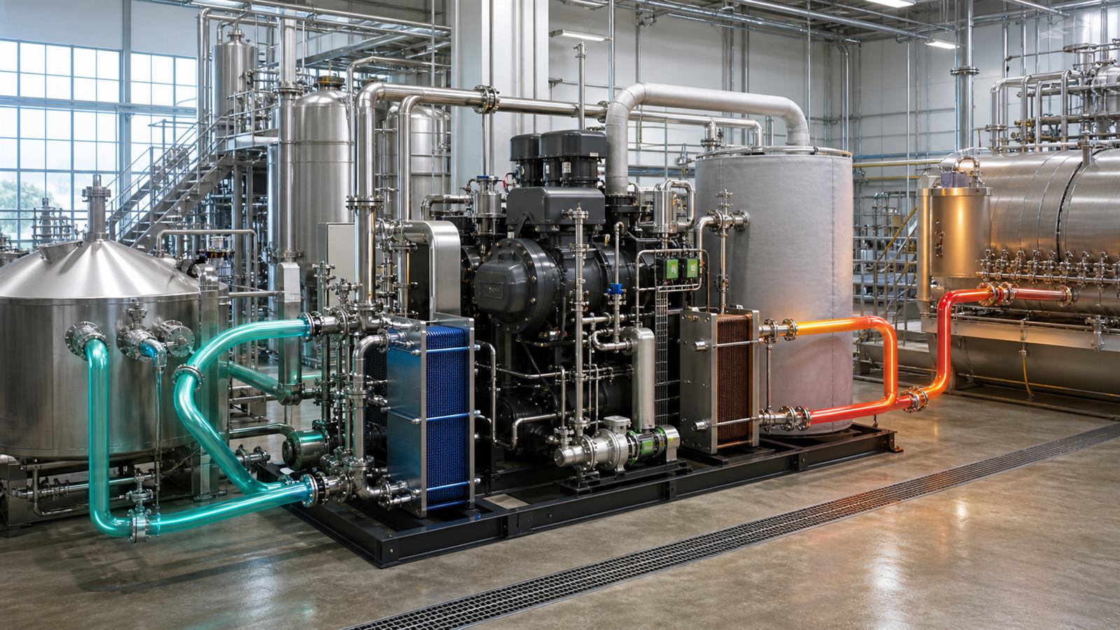
    Mechanical vapor recompression is a related approach that compresses process vapor so it can be reused as a heating medium. It can be highly effective in evaporation and distillation when a clean vapor stream is already available. A closed-cycle heat pump can isolate the process from its refrigerant but needs two heat exchangers and their associated temperature differences.

    The DOE’s current industrial demonstration portfolio includes a proposed steam-generating heat-pump project intended to replace natural-gas boiler heat across manufacturing sites. It is a demonstration and negotiation-stage project, not proof that every steam system is ready for identical conversion.

    Refrigerants set pressure, safety, and climate requirements

    Higher delivery temperatures narrow the choice of working fluids. Designers need suitable thermodynamic properties, manageable pressures, material compatibility, compressor lubrication, and stable operation. Refrigerants also differ in flammability, toxicity, ozone impact, and global-warming potential.

    Natural refrigerants such as carbon dioxide, ammonia, hydrocarbons, or water can work in selected designs, while newer synthetic fluids target lower climate impact. None is universally best. Machinery rooms, ventilation, leak detection, pressure relief, zoning, and worker training must match the chosen fluid and local code.

    Factory reliability changes the design

    Process heating may run for months with little tolerance for interruption. Fouling in a heat exchanger, unstable waste-heat flow, compressor maintenance, or a refrigerant leak can stop more than the heat pump. Plants need bypasses, backup heat, isolation valves, spare-parts plans, and controls that fail into a known production state.

    Source quality matters too. Dirty exhaust or corrosive liquid may require an intermediate loop so contamination cannot reach expensive equipment. That extra heat exchanger protects the machine but adds cost, pumping energy, and temperature loss.

    Performance monitoring should separate compressor electricity from pumps, fans, cooling towers, and backup boilers. Metering source heat, delivered heat, temperatures, flows, and downtime is necessary to verify annual savings.

    Current maturity ends below the hottest processes

    The IEA Heat Pump Monitor 2026 says industrial heat pumps below 120 degrees Celsius have entered commercial operation, with systems below 160 degrees beginning commercial deployment. Higher temperature levels remain largely in demonstration, prototype, or concept stages.

    Those bands will move as compressors, refrigerants, and system designs improve, but the distinction prevents a laboratory outlet-temperature record from being mistaken for a proven factory product. Capacity, hours, maintenance, and delivered efficiency under real process conditions still need evidence.

    Economics depend on energy prices and operating hours

    Capital cost includes much more than the heat-pump skid. Site engineering, shutdowns, piping, electrical upgrades, civil work, controls, and backup equipment can be substantial. Operating cost depends mainly on COP, electricity price, avoided fuel price, maintenance, and annual load factor.

    A plant that simultaneously needs cooling and heating can gain on both sides of the cycle. A site with cheap waste heat but expensive electricity may not. Carbon prices, renewable electricity contracts, demand charges, and incentives can change the result without changing the machine.

    Large electrical loads also need a secure grid connection. The pressure that industrial electrification places on transformer supply and grid capacity should be evaluated early, not after mechanical design is complete.

    How to evaluate an industrial heat-pump proposal

    Ask for hourly source and sink temperature profiles, required heat duty, expected COP across the operating map, annual run hours, auxiliary power, refrigerant, backup strategy, and measured performance at comparable scale. Confirm whether the quoted outlet temperature is available at full capacity or only at a reduced test point.

    Compare the project against efficiency improvements, direct heat recovery, electric boilers, thermal storage, and process redesign. Include shutdown risk, product constraints, grid upgrades, maintenance skills, and emissions from the actual electricity mix.

    What to watch next

    The important advances will be verified high-temperature compressor packages, low-impact refrigerants, standardized testing, steam-generating demonstrations, and repeatable integration designs for food, paper, chemicals, and district heat. Thermal storage and flexible controls may also let plants shift electricity use without disrupting production.

    Industrial heat pumps can make electrification far more efficient than direct heating in the right temperature range. Their success will be measured by reliable annual process heat, not by the hottest outlet achieved for a few minutes.

    Primary and authoritative sources

  • HVDC Transmission Is Becoming the Controlled Backbone of Regional Grids

    HVDC Transmission Is Becoming the Controlled Backbone of Regional Grids

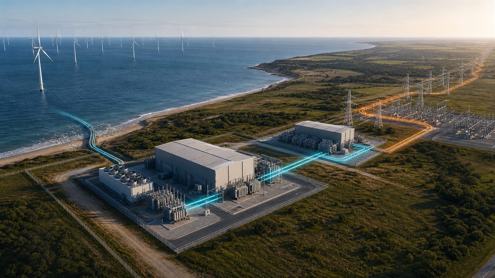
    Electricity grids use alternating current because it is easy to transform between voltages and works well across interconnected networks. Yet some of the largest new transmission projects deliberately convert that electricity to direct current, move it hundreds of kilometers, then convert it back. High-voltage direct current, or HVDC, is becoming a strategic tool for connecting remote generation, submarine cables, and power systems that do not operate in synchronism.

    HVDC is not automatically better than high-voltage alternating current. Converter stations are large, costly, and complex. The technology earns its place when controllable power flow, long distance, cable physics, or asynchronous grids outweigh those terminal costs.

    An HVDC link begins and ends with conversion

    A point-to-point link has a converter station at each end. The sending station takes three-phase AC from a regional grid, transforms it to the required voltage, and uses power-electronic valves to create DC. Conductors carry the direct current to the receiving station, which reconstructs AC synchronized with the destination network.

    Older line-commutated converters use thyristor valves and depend strongly on the connected AC system. Modern voltage-source converters use controllable semiconductor switches that can regulate active and reactive power more independently. VSC systems are attractive for offshore wind, weak grids, underground cables, and future multi-terminal networks, although equipment losses, cost, control, and protection remain significant.

    The US Department of Energy’s Advanced Transmission Technologies report describes HVDC as a direct-current power-flow-control technology used for bulk transfer over long distances and between asynchronous AC systems. That controllability is central: operators can order a link to move a defined amount of power rather than let flow follow AC network impedance alone.

    Direct current has an advantage in long cables

    AC cables continuously charge and discharge their capacitance as voltage reverses. That reactive current consumes cable capacity even when it delivers no net energy to the far end. The effect becomes especially restrictive in long submarine and underground cables. DC avoids this alternating charging current after the line reaches operating voltage.

    HVDC can therefore transmit more useful power through a long cable and control its direction precisely. This is why many offshore wind connections and international submarine interconnectors use DC. It can also use fewer conductors for a given transfer design and may have lower losses over a sufficiently long route.

    The break-even distance is project-specific. Converter stations add costs and losses that an AC line may avoid. Route type, voltage, power rating, cable or overhead construction, permits, land, reliability criteria, and financing all influence the choice. DOE’s overview, Connecting the Country with HVDC, presents indicative distance comparisons while emphasizing the value of long-range efficiency and asynchronous connection.

    HVDC can connect grids that run independently

    Two AC systems can operate at the same nominal frequency without their electrical phase being locked together. Directly tying them with an AC line would require synchronized operation and coordinated stability controls. An HVDC link separates the AC waveforms: one converter takes power from the source, the DC line transfers energy, and the other creates an AC waveform suitable for the destination.

    This allows energy exchange between asynchronous regions and gives operators a controllable interface during disturbances. In the United States, DC links can bridge major interconnections. In Europe, submarine interconnectors move power among countries and support trade, reserves, and renewable balancing.

    Controllability does not make capacity unlimited. Each converter, cable, and connected AC network has thermal, voltage, stability, and contingency limits. Market rules must determine who schedules the link, how congestion is priced, and which system receives support during an emergency.

    Power electronics can support the surrounding AC grid

    A voltage-source converter can rapidly adjust active power and exchange reactive power to help control voltage. Depending on design and grid conditions, it can contribute to frequency response, oscillation damping, restoration, and support for a weak offshore or remote network.

    Those services depend on control software, measurements, communication, and agreed operating modes. A converter cannot replace every function of synchronous generation automatically. Grid-forming behavior, fault response, protection coordination, and restoration capability need to be specified and tested for the connected system.

    Europe’s Network Code on HVDC Connections establishes requirements for long-distance DC links and DC-connected power-park modules. Such rules matter because the converter becomes an active participant in system stability, not merely an electrical adapter.

    DC faults are fast and difficult to interrupt

    AC current naturally crosses zero every cycle, giving conventional breakers an opportunity to extinguish an arc. DC has no periodic zero crossing. A fault can draw energy from the line, converter capacitors, and connected systems while current rises rapidly.

    Point-to-point links can sometimes block converters and isolate the entire line, but a multi-terminal DC grid needs to separate a faulty branch while healthy paths continue operating. That requires fast detection, selective protection, and specialized DC circuit breakers or alternative architectures. DOE has funded work to reduce the cost of high-voltage DC circuit breakers, reflecting how protection remains a deployment constraint.

    Protection also has a cybersecurity dimension. Converter controls depend on precise measurements and automation. Secure communications, tested fallback behavior, configuration management, and incident recovery are part of reliability even when the power hardware itself is healthy.

    Interoperability becomes harder in multi-vendor networks

    A traditional point-to-point project can be engineered as one integrated system. A larger offshore or continental DC network may connect converters from different suppliers at different times. Their controls must share voltage regulation, power balancing, fault response, and restoration without unstable interaction.

    Common models, interfaces, test procedures, and responsibility boundaries are therefore essential. DOE notes that DC systems do not yet have the same level of component standardization and interoperability as mature AC networks. Without progress, owners risk supplier lock-in or expensive custom integration whenever a network expands.

    Supply chains and planning can dominate the schedule

    Converter transformers, valve modules, power semiconductors, bushings, cable, switchgear, cooling equipment, and control systems are specialized products. Large projects compete for engineering capacity and manufacturing slots. The International Energy Agency’s transmission-grid report describes broader supply-chain pressure, long procurement cycles, and the need for coordinated planning.

    HVDC projects also cross jurisdictions, shorelines, communities, markets, and utility territories. Route approval, environmental review, cost allocation, connection studies, and contracts can take longer than hardware installation. The same planning bottleneck appears in our coverage of interconnection queues: useful equipment cannot deliver value before institutions decide where and how it connects.

    HVDC complements rather than replaces the AC grid

    Most generation, distribution, and customer equipment will remain connected through AC networks. HVDC acts as a controlled corridor or interface within that system. Strong AC substations, transformers, protection, and local transmission are still needed to collect power at one end and distribute it at the other.

    This is why the manufacturing constraints discussed in our article on grid transformers remain relevant. Converter transformers are specialized, and receiving regions may need conventional upgrades before they can absorb a large new injection.

    Grid-enhancing technologies can increase use of existing lines more quickly, but they solve another layer of the problem. Dynamic line ratings can reveal additional safe AC capacity under favorable conditions; they do not create a new long-distance corridor across an ocean or between asynchronous systems.

    What a credible project should disclose

    Important facts include power rating, voltage, route length, cable versus overhead construction, converter technology, expected losses, availability target, connected-grid strength, contingency design, reactive-power capability, and restoration plan. Cost comparisons should include both terminals and the network upgrades around them.

    Developers should explain protection strategy, spare equipment, vendor interoperability, cyber controls, environmental impacts, community benefits, and who pays when the link is unavailable. A projected renewable-energy transfer is not the same as measured annual delivery after curtailment, outages, and market constraints.

    What to watch next

    Watch for lower-cost voltage-source converters, proven DC breakers, multi-vendor interoperability tests, expandable offshore grids, and coordinated planning across national and regional boundaries. Public operating data from completed links will help compare availability, losses, support services, and maintenance.

    HVDC is valuable because it gives planners a controllable way to move large amounts of electricity across physical and electrical boundaries. Its success depends less on a single cable record than on converter reliability, protection, standards, supply chains, permits, and the strength of the AC grids at both ends.

    Primary and authoritative sources

  • Electrolyzers Need Flexible Operation Without Trading Away Durability

    Electrolyzers Need Flexible Operation Without Trading Away Durability

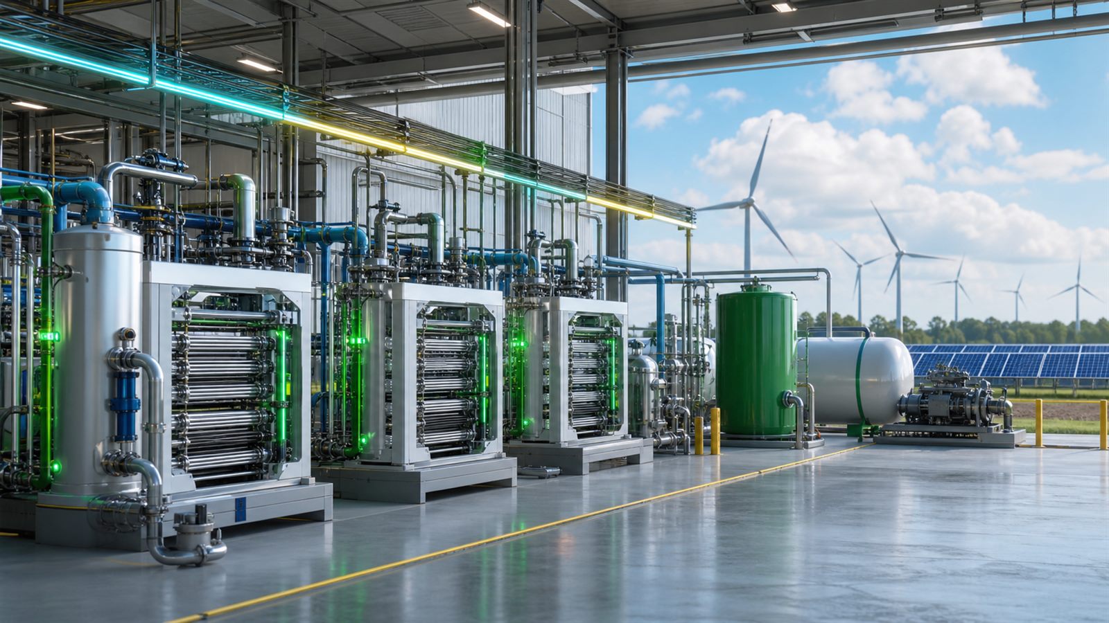
    Electrolyzers can turn electricity and water into hydrogen, which makes them tempting partners for wind and solar farms. When renewable generation rises, the plant can increase production; when power becomes scarce or expensive, it can reduce load. That flexibility sounds like a natural match, but an electrolyzer is an electrochemical factory rather than a perfectly responsive battery.

    Frequent starts, stops, and changes in power can affect efficiency, gas purity, temperature, pressure, catalysts, membranes, and downstream equipment. A plant designed to absorb variable electricity therefore needs more than a fast control signal. It needs hardware, storage, operating limits, and an economic plan that preserve stack life while still producing useful volumes of low-emissions hydrogen.

    Hydrogen is only as clean as its electricity

    Electrolysis splits water into hydrogen and oxygen using electricity. The process does not produce carbon dioxide at the stack, but its full emissions depend heavily on where the electricity comes from and when it is consumed. The US Department of Energy’s electrolysis overview emphasizes that electricity source, cost, efficiency, and associated emissions all belong in the assessment.

    This is why flexibility matters. A plant may be able to favor hours with abundant wind, solar, hydro, or nuclear generation. It can potentially use electricity that would otherwise be curtailed. But a low annual average price or emissions figure can hide the actual hourly pattern. Claims about renewable hydrogen need matching rules and operating data that show when the electrolyzer ran, not merely the nameplate capacity of a nearby generator.

    The main electrolyzer families respond differently

    Proton exchange membrane, or PEM, electrolyzers use a solid polymer membrane and can respond quickly across a useful operating range. They are attractive for variable power, but today’s designs rely on scarce platinum-group materials, especially iridium at the oxygen-producing electrode. Lowering catalyst loading can reduce material constraints while making durability more demanding.

    Liquid alkaline electrolyzers use a liquid electrolyte and are a mature industrial option. They can be economical at scale, although their minimum load, gas crossover, pressure behavior, and response depend on design. Solid oxide electrolyzers operate at high temperature and can achieve high electrical efficiency when heat is available. Thermal management makes abrupt cycling a different challenge than it is for a low-temperature stack.

    No family is universally “best for renewables.” The answer depends on the power profile, hydrogen demand, heat source, operating pressure, water quality, plant size, and how often the system crosses its preferred operating region.

    Flexible load is not the same as unlimited cycling

    Within an approved operating window, an electrolyzer can ramp power and provide a controllable industrial load. Problems emerge when a schedule repeatedly pushes cells through high voltage, low load, shutdown, restart, pressure change, or temperature transition. Components experience different chemical and mechanical stresses, and some degradation mechanisms accumulate faster under cycling.

    A peer-reviewed national-laboratory study of PEM cells at low iridium loading found that cycling accelerated performance loss compared with steady operation. Model wind and solar profiles were less severe than artificial high-frequency square and triangle cycles, showing why a realistic duty cycle matters. The researchers linked losses to iridium dissolution and changes around the catalyst layer, and concluded that both component development and control strategies are needed.

    That result should not be simplified into “renewables damage electrolyzers.” Actual renewable profiles, control smoothing, standby choices, and stack design determine the stress. It does show why a durability claim based only on constant full-power operation may not predict life in a flexible plant.

    Efficiency changes across the operating range

    An electrolyzer’s headline efficiency is usually measured at specified current density and conditions. At part load, some electrical losses decline, while fixed auxiliary loads such as pumps, controls, cooling, water treatment, and compression become larger relative to hydrogen output. At very low load, gas crossover can affect purity and safe operation. Starting a hot or pressurized system also differs from starting a cold plant.

    The useful metric is therefore a plant-level efficiency curve, not one stack point. Operators need to know electricity consumed per unit of delivered hydrogen across load, including balance-of-plant equipment. If downstream compression or synthesis equipment prefers stable flow, aggressively following every power fluctuation at the stack may simply move inefficiency elsewhere.

    Buffers can separate power variability from hydrogen demand

    A small battery, thermal buffer, hydrogen storage vessel, or multiple independently controlled stack modules can smooth operation. The electrolyzer may follow slower renewable changes while a battery handles rapid fluctuations. Hydrogen storage can let downstream users receive a steadier flow even when production varies. Modular plants can keep some stacks near efficient operating points while others turn down.

    Each buffer has a cost and loss, so the goal is not to make the plant perfectly steady. The goal is to assign each timescale to the component that handles it economically. This is related to the broader point in our guide to long-duration energy storage: different technologies solve different durations, locations, and output needs.

    Grid conditions also matter. Dynamic line ratings can reveal temporary transmission capacity, but they do not guarantee that power is available at an electrolyzer’s connection point. Interconnection limits, congestion, and local network upgrades can determine whether flexible demand is useful to the grid.

    Durability has to be measured as a system target

    The Department of Energy’s H2NEW consortium tracks capital cost, efficiency, and lifetime together across PEM, alkaline, and solid oxide technologies. Its public goals illustrate an important discipline: a low stack cost is not enough if the system degrades quickly, and a long-lived stack is not enough if it consumes too much electricity.

    Manufacturers and projects should report the duty cycle behind a lifetime estimate. Useful information includes operating hours, starts, time at low load, ramp rate, average current density, water quality, pressure, temperature, replacement assumptions, and the end-of-life criterion. Accelerated stress tests are valuable only when they have a defensible relationship to field operation.

    Balance-of-plant equipment needs the same attention. Rectifiers, pumps, dryers, separators, compressors, valves, sensors, and storage vessels can limit availability even when the electrochemical stack is healthy. A flexible hydrogen plant is a coordinated process facility, not one stack connected directly to a wind turbine.

    The business model determines the operating schedule

    A project buying only the cheapest hours may reduce electricity expense but also lower utilization, spreading capital cost over fewer kilograms of hydrogen. Running continuously can improve asset utilization while consuming higher-priced or higher-emissions electricity. Providing grid services may create another revenue stream, but it can impose additional movement on the equipment.

    The optimum schedule depends on power prices, carbon accounting, hydrogen contracts, storage capacity, maintenance, and degradation cost. It should include the value of stack life rather than treating every megawatt-hour as interchangeable. Better control software can optimize these choices, but only if it uses validated equipment limits and does not confuse a short demonstration with long-term durability.

    Electrolyzers can complement technologies such as grid-forming inverters, yet they serve a different role. An inverter can help stabilize an electricity system on very fast timescales. Hydrogen production converts energy into a storable molecule for industry, transport, or later energy use, with more conversion steps and different response constraints.

    Limitations buyers should notice

    Project announcements often quote rated efficiency, expected lifetime, or renewable capacity without showing whether the figures apply simultaneously. A plant may reach excellent efficiency under stable operation and excellent flexibility under a different test. Cost estimates may omit installation, interconnection, storage, compression, water treatment, or replacement stacks.

    What to watch next

    The most informative demonstrations will publish multi-thousand-hour results under realistic renewable and market duty cycles. Watch for lower catalyst loading paired with stable performance, validated accelerated stress tests, plant-level efficiency curves, modular control strategies, and transparent maintenance records. Projects should also report hourly electricity provenance and delivered-hydrogen conditions rather than only annual averages.

    Flexible electrolysis can turn variable electricity into a controllable industrial process, but flexibility is not free. The strongest systems will decide which fluctuations to follow, which to buffer, and which to ignore. Success will come from optimizing electricity cost, emissions, hydrogen delivery, and equipment life together.

    Primary and authoritative sources

  • Grid Transformers Are a Manufacturing Constraint on Electrification

    Grid Transformers Are a Manufacturing Constraint on Electrification

    Electrification is often described as a race to build batteries, renewable generators, transmission lines, and data centers. A less glamorous component can still decide when those projects connect: the transformer. Transformers change voltage so electricity can move efficiently across the grid and then reach homes, factories, chargers, and computing facilities at usable levels.

    Utilities report long waits for many transformer classes, but the problem is not simply a shortage of metal boxes. Transformers combine specialized electrical steel, conductors, insulation, precision assembly, testing, utility-specific requirements, and difficult logistics. Expanding output requires coordinated changes across a manufacturing system.

    Transformers make a multi-voltage grid possible

    Power plants and renewable projects generate electricity at one voltage, long-distance networks transmit it at much higher voltages, and local equipment uses lower voltages. A transformer transfers energy between circuits through a magnetic core and windings. It has no continuously moving mechanical parts, but small design choices influence efficiency, temperature, sound, insulation life, and fault tolerance.

    A distribution transformer typically makes the final voltage conversion near customers. Larger power transformers connect major substations and transmission systems. They are not interchangeable products; their engineering, transport, testing, and replacement strategies differ substantially.

    Electrification increases demand from several directions

    New housing, industrial expansion, electric heating, vehicle charging, renewable generation, storage, and data centers all create connection work. Aging equipment also needs replacement. A utility may therefore be ordering for normal maintenance, storm recovery, new loads, grid modernization, and resilience at the same time.

    The US Department of Energy has been studying transformer demand, age profiles, manufacturing capacity, and material constraints with support from the National Renewable Energy Laboratory. That matters because a national headline about electricity growth does not translate directly into a count of transformer models. Location, voltage, phase, capacity, mounting style, protection, and utility practice determine the actual order.

    A highly customized market is hard to scale

    DOE’s supply-chain analysis identified more than 80,000 distribution-transformer varieties and noted that inconsistent utility specifications contribute to longer production times. Many differences have valid technical origins, including local network design, climate, safety rules, loading assumptions, and installation equipment. Others can persist because utilities developed procurement standards independently over decades.

    Customization fragments demand into smaller batches. Manufacturers must change tooling, materials, drawings, test plans, and documentation. Utilities may also have to qualify a design or supplier before placing a large order.

    Electrical steel is a strategic input

    The magnetic core is made from thin laminations of electrical steel engineered to reduce energy losses. Grain-oriented electrical steel is especially important in many transformer designs. Its production requires specialized metallurgical processing and equipment, so capacity cannot be expanded as quickly as ordinary sheet steel.

    Core geometry and material grade affect efficiency, dimensions, weight, sound, and cost. Manufacturers also need reliable supplies of conductor metal, insulating paper, fluids, bushings, tanks, controls, and other components. A shortage or qualification delay in one item can hold an otherwise complete unit at the factory.

    Efficiency rules interact with manufacturing capacity

    More efficient transformers reduce losses over decades of operation, saving energy across millions of units. However, a revised efficiency requirement can also change core materials, dimensions, tooling, and qualification work. The timing of a standard therefore matters to both energy savings and the industry’s ability to deliver equipment.

    In 2024, DOE finalized amended US efficiency standards for distribution transformers that take effect in 2029. In 2026, the department sought further information about manufacturing capacity, materials, and supply-chain resilience. The policy question is not whether efficiency or availability matters more. It is how to plan a transition that improves lifetime performance while suppliers expand the necessary production capability.

    Manufacturing is precision work, not simple enclosure assembly

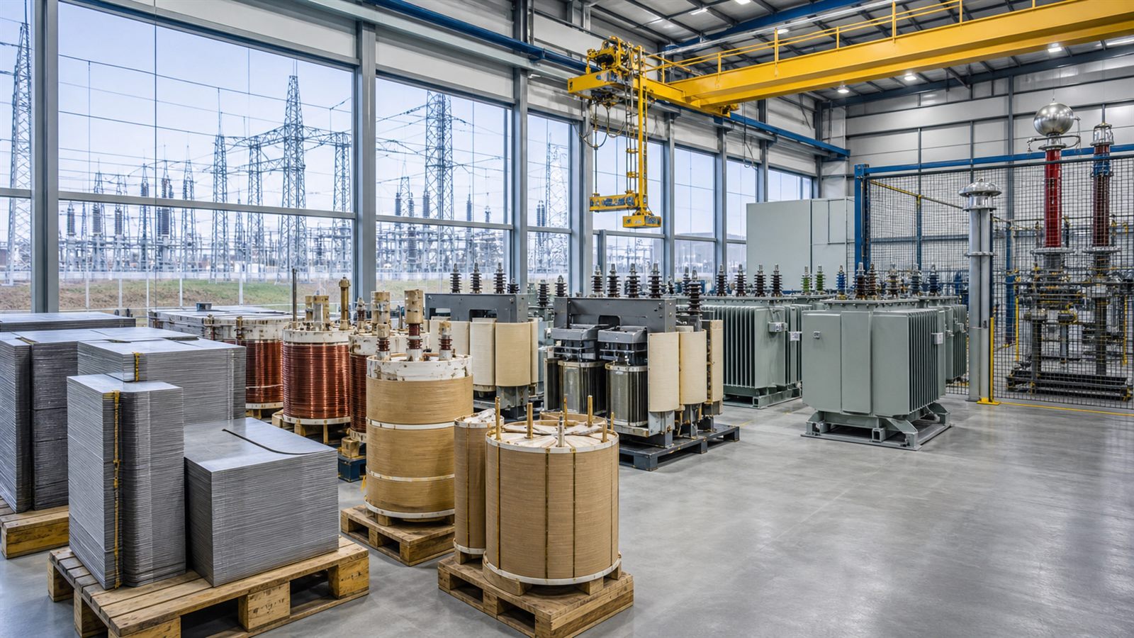
    Steel laminations must be formed and stacked into a low-loss magnetic path. Conductors are wound into coils, dried, insulated, assembled around the core, connected, enclosed, and filled or otherwise prepared for thermal management. Moisture, contamination, mechanical alignment, and insulation defects can shorten life or cause a failure under high electrical stress.

    Finished units undergo electrical and mechanical tests appropriate to their class. Large power transformers are often engineered for a particular substation and can take a long time to design, build, test, ship, and commission. Adding buildings is not enough; manufacturers also need skilled workers, winding and core equipment, test bays, quality systems, and dependable upstream suppliers.

    Transport can become part of the engineering

    A pole-mounted distribution transformer can move through familiar freight networks. A large power transformer may require special railcars, heavy-haul trailers, bridge studies, road closures, lifting plans, and site preparation. Some accessories travel separately and are installed after the main tank arrives.

    This makes replacement planning different from ordering ordinary industrial hardware. A spare is useful only if it matches the required electrical role and can physically reach the site. Regional sharing programs, transport-ready designs, and preplanned routes can improve resilience, but they cannot eliminate every compatibility constraint.

    Standardization could enlarge production runs

    Utilities do not need to erase every local difference to gain scale. They can identify which specifications are essential and which can be harmonized across multiple buyers. Common ratings, interfaces, accessories, test documentation, and procurement language could support larger production batches and more supplier competition.

    Standardization requires engineering work and governance. A common model must still tolerate expected loads, weather, faults, and maintenance practices. It may also require changes to utility inventories and field equipment. The payoff is a market in which capacity investments have clearer demand and replacement units can serve more locations.

    Better forecasting can reduce boom-and-bust investment risk

    Manufacturers hesitate to finance long-lived capacity when orders are uncertain. Utilities, regulators, developers, and governments can improve visibility by sharing credible multiyear demand ranges and project schedules. Aggregated procurement can support investment.

    Forecasts must account for cancellations and delays. The presence of a project in an interconnection queue does not guarantee construction. Scenarios are more useful than one precise number because data-center growth, electrification policy, housing, interest rates, and local permitting can all change actual demand.

    Utilities can manage risk before equipment arrives

    Asset-health monitoring can identify transformers that need attention before failure. Loading studies can show whether an existing unit has usable capacity, while maintenance can extend service life where safe. Strategic spares can reduce outage exposure.

    Grid-enhancing technologies also help utilities use existing infrastructure more effectively. Dynamic line ratings can reveal additional transmission capacity under favorable conditions. These measures do not remove the need for transformers, but they can improve sequencing and keep scarce equipment focused on the projects that truly require it.

    Transformer availability shapes the clean-energy timeline

    A solar farm, battery site, factory, or charging depot may be technically complete yet unable to energize until substation equipment is ready. The resulting delay raises financing costs and can hide behind broader labels such as permitting or interconnection. Tracking critical equipment separately makes project schedules more realistic.

    Transformers also work with power-electronic equipment. As renewable penetration grows, grid-forming inverters may support voltage and frequency, but they still connect into a physical network with voltage-conversion, protection, and thermal limits. Digital controls cannot manufacture missing hardware.

    Limitations

    Lead times vary widely by transformer class, specification, supplier, buyer, and market conditions. DOE reported that US distribution-transformer lead times rose from roughly three to six months in 2019 to about 12 to 30 months in 2023, but those figures should not be treated as a permanent quote for every order in 2026. Commercial terms and factory schedules continue to change.

    Standardization is also not a universal cure. Overly rigid designs can perform poorly in unusual climates or network configurations. Domestic production can improve resilience without making global supply relationships irrelevant. A durable strategy needs material diversity, qualified suppliers, workforce development, demand visibility, and emergency planning.

    What to watch next

    Watch for expansion of electrical-steel and transformer plants, utility specification harmonization, multiyear procurement agreements, workforce and test-bay investment, and evidence that announced capacity is producing qualified equipment. DOE’s distribution-transformer working group and standards process should reveal how efficiency, materials, and supply resilience are balanced.

    The transformer shortage is best understood as an industrial coordination problem. Electrification will move faster when the grid’s most ordinary-looking equipment is treated as strategic manufacturing infrastructure.

    Sources: US Department of Energy Supply Chain and Market Analysis; DOE research on distribution-transformer types and demand drivers; DOE 2026 request for information on distribution-transformer standards and supply chains; DOE Electric Grid Supply Chain Deep Dive Assessment.

  • Dynamic Line Ratings Can Unlock Grid Capacity, but They Cannot Replace New Transmission

    Dynamic Line Ratings Can Unlock Grid Capacity, but They Cannot Replace New Transmission

    Electric transmission lines do not have one permanent carrying capacity. Their safe limit changes with conductor temperature, wind, sunlight, and the amount a wire sags toward the ground. Yet many power systems have historically operated lines using conservative static or seasonal ratings based on assumed conditions.

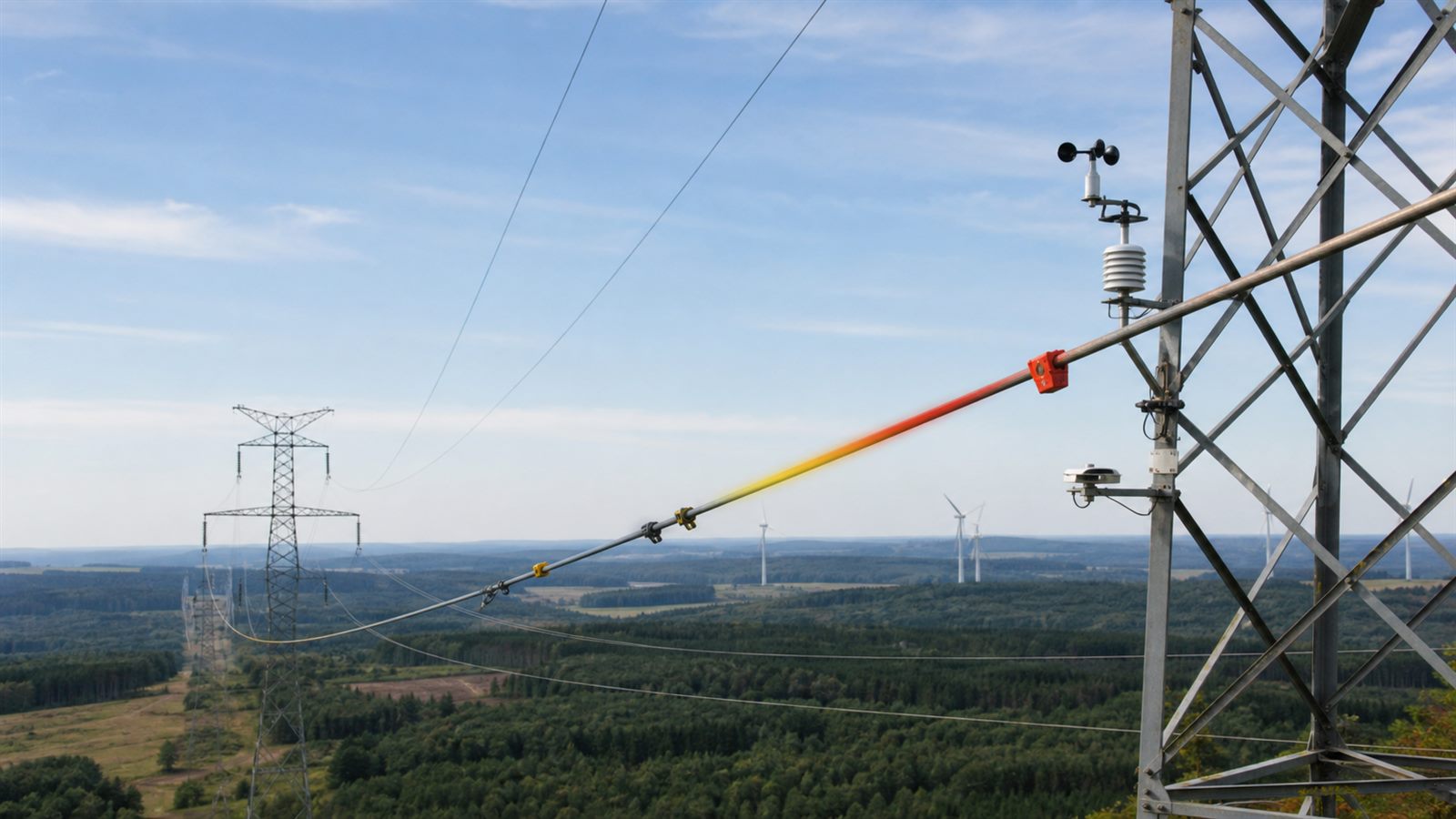
    Dynamic line rating, or DLR, replaces part of that assumption with current measurements and forecasts. It can reveal additional capacity when cool air or wind removes heat from a conductor, and it can reduce the rating when conditions are hotter or calmer than expected. That makes DLR a valuable grid tool, but not a substitute for every new power line.

    A transmission rating is a safety boundary

    Current heats a conductor. As the wire warms, it expands and sags. Excess heat can also accelerate material aging and stress connected equipment. Operators set a line rating to keep conductor temperature, ground clearance, and equipment loading within safe limits while respecting voltage and stability constraints elsewhere on the network.

    A static rating uses a conservative set of environmental assumptions. A seasonal rating changes a few times per year. These methods are simple and predictable, but they can understate capacity during cool, windy periods and can be less accurate during unusual conditions.

    Ambient-adjusted and dynamic ratings are different

    An ambient-adjusted rating updates the limit using forecast air temperature, often at hourly intervals. A dynamic rating can incorporate additional inputs such as wind speed and direction, solar heating, precipitation, conductor temperature, tension, or measured sag. FERC defines DLR as applying to a period no longer than one hour and reflecting up-to-date forecasts of relevant inputs.

    The distinction matters in regulation. FERC Order 881 required ambient-adjusted ratings for many near-term transmission decisions and required regional operators to support at least hourly electronic rating updates. It did not broadly mandate that every transmission owner deploy full DLR. A later inquiry examined where deeper requirements could be justified.

    Sensors and models work together

    A DLR installation may use weather stations, conductor-temperature sensors, tension monitors, sag measurement, or remote observations. Software combines those inputs with conductor properties and an engineering thermal model to calculate a safe current limit. Forecasts extend the rating beyond the immediate measurement so operators can plan dispatch.

    No single sensor represents an entire long corridor. Terrain, vegetation, tower geometry, and local wind can change along the route. Engineers need enough coverage to identify the limiting span, plus quality checks that detect a failed sensor or implausible value. Conservative fallback ratings remain essential when data are missing.

    Where DLR creates the most value

    DLR is most useful when conductor heating is the binding limit and weather frequently provides more cooling than the static assumption. Wind generation can create a helpful correlation: the same wind producing electricity may cool nearby lines, allowing more output to move. Congested corridors with large price differences may gain substantial operational value from a modest increase in capacity.

    The Department of Energy has highlighted utility deployments that reported increased line capacity and avoided or deferred some upgrades. These are project-specific outcomes, not a universal percentage. Every corridor needs its own weather record, power-flow analysis, sensor design, and economic case.

    More accurate can also mean lower

    Dynamic does not always mean higher. On a hot, still, sunny day, the calculated capacity may fall below a seasonal assumption. That is a feature of accurate operation, not a failure. Operators must be prepared to redispatch generation or reduce flows when the rating changes.

    Forecast uncertainty matters because power schedules are arranged before real-time conditions are known. A useful system should report confidence, apply margins, and prevent frequent rating swings from destabilizing operations. Grid control rooms also need procedures that explain when an automated rating may be overridden.

    Telemetry becomes reliability infrastructure

    Once a sensor changes an operational limit, its communications and software become part of a safety-critical system. Authentication, time synchronization, calibration, maintenance, audit logs, and cyber incident response all matter. A false high reading could create unsafe loading, while a false low reading could cause unnecessary congestion.

    Utilities therefore need diverse data checks and a safe fallback rather than trusting one internet-connected device. This mirrors the broader lesson from grid-forming inverter controls: software can provide valuable grid behavior only when protection and validation are engineered around it.

    DLR cannot remove every bottleneck

    A corridor may be limited by transformers, breakers, voltage, transient stability, or another line rather than conductor temperature. Increasing one rating can simply move congestion to the next element. DLR also cannot create much extra capacity during extended hot, calm conditions, precisely when demand may be high.

    Long-term load growth and new generation still require new lines, reconductoring, substations, storage, and other investments. The interconnection queue problem is too large to solve with one sensor technology. DLR is best treated as part of a portfolio that also includes power-flow control, topology optimization, advanced conductors, and transmission expansion.

    Planning rules are beginning to recognize grid-enhancing technology

    DOE describes dynamic ratings as one form of grid-enhancing technology, alongside tools that redirect power or optimize network configuration. FERC Order 1920 requires transmission providers to consider certain alternative transmission technologies, including DLR, in long-term regional planning processes. Consideration does not mean automatic selection; planners still compare costs, reliability, deployment time, and expected benefits.

    This creates a useful discipline. A proposed new line should be compared with ways to use existing infrastructure better, while a software proposal should be tested against realistic future demand. Energy storage can complement both approaches, as explained in our guide to the long-duration storage technology portfolio.

    Limitations

    DLR performance is location-specific, and pilot results may not transfer to another climate or corridor. Installation and communications are faster than building a new line but still require engineering, outages, integration, training, and continuing maintenance. Public benefit estimates depend on market rules and which generator would otherwise be curtailed.

    Weather data also have limits. Forecast errors, icing, wildfire conditions, sensor drift, and changing vegetation can require special treatment. Ratings should remain conservative where evidence is weak.

    What to watch next

    Watch for regional operators to publish more hourly rating data, planners to compare DLR with reconductoring and new construction, and utilities to report multi-year performance rather than only pilot peaks. Standards for telemetry, uncertainty, cybersecurity, and fallback operation will be as important as sensor accuracy.

    Dynamic line ratings can make the grid more aware of its real physical capacity. Their value is greatest when that awareness is paired with new infrastructure, not used as an excuse to postpone it indefinitely.

    Sources: FERC: Implementation of Dynamic Line Ratings; U.S. Department of Energy: Smart Transmission Tools; NREL: On the Road to Increased Transmission; U.S. Department of Energy: Grid-Enhancing Technologies.

  • Long-Duration Energy Storage Is a Technology Portfolio, Not One Giant Battery

    Long-Duration Energy Storage Is a Technology Portfolio, Not One Giant Battery

    Battery storage is becoming a familiar part of modern electricity grids, but most grid batteries are designed to shift energy across a limited part of the day. A system that covers an evening peak is solving a different problem from one that must carry critical loads through a long shortage of wind or sunlight. That is where long-duration energy storage, usually shortened to LDES, enters the conversation.

    The important idea is not simply a battery that runs longer. Long-duration storage is a portfolio of electrochemical, mechanical, thermal, and chemical approaches, each with different costs, efficiencies, locations, and operating limits. The right technology depends on the grid service being purchased, not on which storage chemistry has the most dramatic headline.

    Long duration is a grid requirement, not one fixed number

    The US Department of Energy commonly defines LDES as storage that can deliver electricity for 10 hours or more. That is a useful program boundary, but it is not a universal engineering answer. A National Renewable Energy Laboratory study found that the duration needed for firm capacity can vary from a few hours to multiple days depending on the power system and the job storage must perform.

    This distinction prevents a common mistake. Duration is calculated by comparing the energy a system can store with its maximum power output. A plant may discharge at high power for a short period or at lower power for much longer. Neither configuration is automatically better. A utility first needs to identify the shortage, ramp, congestion, or resilience problem it is trying to solve.

    Why four-hour batteries do not solve every problem

    Lithium-ion batteries are effective for fast response, frequency control, and moving solar generation into the evening. But adding more hours can require proportionally more battery cells, which may make a different architecture more attractive. A storage system designed around inexpensive energy capacity can be useful when long discharge time matters more than a compact footprint.

    The grid also changes as storage is added. Early batteries can target the highest-value short peaks. As more of those peaks are covered, the remaining periods of tight supply may become longer or occur less often. That is one reason NREL warns against treating “long duration” as a static label. Storage value depends on the future mix of generation, transmission, flexible demand, and other storage.

    A portfolio is emerging

    Flow batteries store energy in liquid electrolytes held in tanks. Their power hardware and energy tanks can be sized somewhat independently, which is attractive for longer discharge times. Other electrochemical systems use abundant materials such as zinc, iron, or lead in designs intended for stationary storage. Each approach still has to demonstrate lifetime, efficiency, manufacturing quality, and safe operation at scale.

    Mechanical systems include pumped hydropower and compressed-air storage. They can move large amounts of energy, but geography, permitting, construction time, and site design are central constraints. Thermal systems store heat in materials such as molten salts, rocks, or carbon blocks and later use that heat directly or convert it back to electricity. Chemical storage, including hydrogen-based pathways, may support very long or seasonal time scales, although conversion losses and infrastructure requirements can be substantial.

    This variety is a strength, not evidence that one winner has been missed. Different grids may need different combinations. A dense city, an isolated microgrid, a region with suitable underground formations, and an industrial site that can use heat directly do not face the same design problem.

    The most important metric may not be efficiency

    Round-trip efficiency measures how much electricity returns after charging and discharging losses. It matters, especially for storage that cycles frequently. But an efficient system with expensive energy capacity may not be the best choice for a rare multi-day event. A lower-efficiency technology could still be useful if it stores a large amount of energy cheaply, remains ready for long periods, and meets the required reliability.

    Buyers also need to compare response time, cycle life, calendar life, standby losses, minimum operating level, maintenance, land use, water needs, fire behavior, supply-chain exposure, and the time required to build a project. Performance should be measured under realistic duty cycles rather than inferred from a laboratory cell or a short demonstration.

    Storage cannot replace the rest of the grid

    Long-duration storage is one flexibility option among several. Transmission can move electricity from a region with surplus generation to one with a shortage. Demand response can shift some consumption. Firm generation can provide power during extended low-renewable periods. Better forecasting and regional coordination can reduce the amount of backup capacity required.

    This is why the transmission bottleneck described in Interconnection Queues Show Clean Energy’s Grid Bottleneck Is Still Real remains relevant. A storage project cannot help if it waits years for a grid connection. Distributed coordination also matters. Virtual Power Plants Turn Small Energy Devices Into Grid Capacity shows how many shorter-duration devices can sometimes provide services that would otherwise require a larger plant.

    Commercial proof is harder than a prototype

    DOE’s LDES portfolio includes pilot and demonstration programs because grid infrastructure needs evidence beyond a working prototype. Developers must prove that systems can be manufactured, permitted, financed, operated, maintained, and insured. Utilities need warranties and degradation data that match the planned use. Regulators need a way to compare a new storage plant with transmission, demand flexibility, generation, and other storage options.

    Revenue is another challenge. A plant built for rare reliability events may provide enormous value during a shortage but earn little in ordinary energy trading. Market rules must recognize capacity, resilience, and other grid services without paying for equipment that cannot perform when needed. That is a policy and planning problem as much as a materials problem.

    Limitations worth keeping in view

    No LDES technology eliminates environmental tradeoffs. Large projects use land, materials, industrial equipment, and grid infrastructure. Mechanical projects may reshape sites. Chemical systems need careful leakage and safety management. Batteries require responsible sourcing and end-of-life plans. Claims about low cost should specify whether they include charging electricity, power conversion, construction, financing, replacement, and decommissioning.

    Storage also does not generate energy. Extended shortages require enough generation and transmission to recharge the system. Complementary clean firm resources, including the geothermal expansion discussed in Enhanced Geothermal Systems Could Expand Clean Energy’s Underground Map, may reduce how much stored energy a region needs.

    What to watch next

    Watch for independently verified performance over several years, clearer safety standards, repeatable project costs, and contracts that pay for the grid service rather than a fashionable technology label. Also watch whether developers can separate the cost of power equipment from the cost of adding more stored energy. That is one of the design advantages long-duration systems often promise.

    LDES is best understood as a planning category, not a single product. Its future will probably be a mix of technologies selected for specific locations and time scales. The strongest projects will be the ones that solve a measured grid problem and can prove their performance outside a presentation.

    Sources: US Department of Energy: Long-Duration Energy Storage; DOE Office of Electricity: Energy Storage; NREL: The Challenge of Defining Long-Duration Energy Storage; DOE: Achieving the Promise of Low-Cost Long Duration Energy Storage.

  • Enhanced Geothermal Systems Could Expand Clean Energy’s Underground Map

    Enhanced Geothermal Systems Could Expand Clean Energy’s Underground Map

    Geothermal energy has a strong appeal: clean heat from the Earth, available day and night, with a smaller land footprint than many other energy sources. The limitation is geography. Traditional geothermal power works best where hot water or steam is naturally accessible. Enhanced geothermal systems, or EGS, aim to expand that map.

    EGS does not wait for a perfect natural reservoir. It uses drilling, stimulation, and reservoir engineering to create or improve pathways through hot rock so fluid can circulate, collect heat, and return to the surface. If it can scale safely and economically, geothermal could become a more flexible clean-energy resource.

    Why Geothermal Is Attractive

    Unlike solar and wind, geothermal power can operate steadily when the resource and plant are available. That makes it useful for firm clean electricity and industrial heat. A grid with more variable generation still needs dependable sources that can run through calm nights and winter peaks.

    The US Department of Energy describes enhanced geothermal systems as a way to access heat in places without naturally productive hydrothermal resources. The technology borrows from oil and gas drilling, reservoir modeling, and power-plant engineering while pursuing a low-carbon purpose.

    This complements our coverage of long-duration energy storage. Storage can shift electricity across time, while geothermal can supply clean power continuously if the resource is developed well.

    That firm-power role is why geothermal keeps returning to policy discussions even when solar, wind, and batteries dominate new project headlines. A system with high renewable penetration needs resources that help through long periods of low wind, low sunlight, or grid stress.

    The Main Engineering Challenge Is the Reservoir

    An EGS project needs hot rock, a way to circulate fluid, and a reservoir that remains productive. Engineers may inject fluid under pressure to open or connect fractures. The goal is enough permeability for heat exchange without losing control of the system.

    That is difficult. If fluid moves too quickly, it may not pick up enough heat. If it flows through too few channels, the reservoir may cool unevenly. If fractures behave unpredictably, performance and safety risks increase.

    Reservoir monitoring therefore matters as much as drilling. Operators need seismic sensors, pressure data, flow measurements, temperature models, and careful operating limits. EGS is not just digging a deep hole; it is managing a subsurface heat exchanger.

    FORGE Is a Major Test Platform

    DOE’s Frontier Observatory for Research in Geothermal Energy, known as Utah FORGE, is a dedicated field laboratory for EGS research. It gives researchers a place to test drilling, stimulation, monitoring, and reservoir-management techniques under real subsurface conditions.

    Field test platforms are important because lab results and simulations cannot capture every feature of hot rock, stress fields, water-rock interactions, and long-term circulation. A technology that looks promising on paper must survive drilling cost, reservoir uncertainty, equipment wear, and operational complexity.

    This is similar to the interconnection reality we covered in clean-energy grid bottlenecks. The energy transition depends on less glamorous engineering infrastructure as much as headline generation technologies.

    Induced Seismicity Must Be Managed

    Any technology that injects fluid underground needs careful seismic risk management. EGS can create small earthquakes as fractures respond to pressure changes. Most may be too small to feel, but public trust depends on transparent monitoring, conservative operations, and clear rules for slowing or stopping activity.

    Risk depends on geology, faults, injection strategy, pressure, volume, and local vulnerability. It cannot be dismissed with generic assurances. Communities need to know what is being measured, what thresholds trigger action, and who is accountable.

    Seismic management does not make EGS impossible. It makes governance and site selection central to deployment. A technically promising resource is not enough if local risk is poorly understood.

    Cost Is Still the Scaling Question

    Drilling deep wells is expensive. EGS projects must improve drilling speed, well durability, reservoir productivity, and plant performance to compete with other clean-energy options. The economics improve if methods can be repeated across many sites rather than custom-engineered each time.

    DOE’s Enhanced Geothermal Shot aims to reduce the cost of EGS substantially. Cost targets are not deployment guarantees, but they clarify the scale of improvement needed.

    Geothermal also has system value that simple energy prices may not fully capture. Firm clean power, heat supply, small land footprint, and use of existing drilling expertise can matter, especially in regions with limited transmission or difficult seasonal demand.

    Oil and Gas Skills Could Help

    EGS can reuse some oil and gas capabilities: drilling, well completion, reservoir characterization, downhole tools, and field operations. That does not mean geothermal is simply oil and gas with a different label. Heat extraction, water management, induced seismicity, and long project lifetimes create different priorities.

    Still, transferable expertise could reduce cost and speed learning. Companies that understand subsurface engineering may be able to improve geothermal drilling and monitoring. The strongest projects will adapt those skills to clean-energy requirements rather than copy fossil-fuel workflows blindly.

    What to Watch Next

    Watch field results from FORGE and commercial pilots, especially flow rates, temperature decline, drilling costs, seismic response, and uptime. Also watch whether projects can move from one successful site to repeatable development across different geology.

    Enhanced geothermal systems are not a universal replacement for solar, wind, batteries, or transmission. They are a possible addition to the clean-energy toolkit. If the reservoir engineering matures, geothermal could provide firm clean energy in more places than traditional geothermal maps suggest.

    For ordinary energy watchers, the useful question is not whether EGS sounds futuristic. It is whether developers can show repeatable wells, stable reservoirs, transparent seismic management, and costs that keep improving across projects rather than resetting with every site.

    Sources and Further Reading