Frontier Technology Portal Independent technology analysis / Updated daily
Frontier Technology Portal logo
FRONTIER Technology Portal for the next wave of invention

Category: Robotics

Robots in factories, homes, hospitals, warehouses, agriculture, and the field.

  • Robot Charging Depends on Reliable Docking, Not Just Battery Size

    Robot Charging Depends on Reliable Docking, Not Just Battery Size

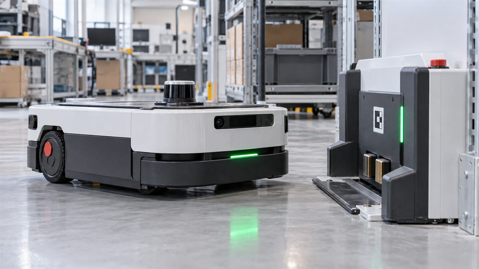
    An autonomous mobile robot can navigate a warehouse aisle beautifully and still spend its last few minutes of battery life nudging a charger without making electrical contact. The trip to the charger and the final centimeters of docking are different engineering problems. A reliable robot must decide when to return, reach a staging position, locate the dock precisely, make contact, confirm charging, and recover when any step fails.

    That is why battery capacity alone does not determine useful operating time. A larger pack may extend a shift, but an unreliable return-to-charge cycle can still strand a machine or demand frequent human intervention. For buyers and curious observers, the better question is not simply how long a robot runs. It is how consistently it can resume work after a complete charge-and-undock cycle.

    Getting near the dock is not the same as docking

    A navigation system can bring the robot to a waypoint near its charger. At that point, the tolerances usually become tighter than those of ordinary travel. The robot may need to align a connector, contact pads, or a mechanical interface while avoiding a hard collision. A map location can be slightly wrong; the charger can move; wheels can slip on a dusty or uneven floor.

    The Nav2 Docking Server tutorial separates the process into navigating to a staging pose, detecting and refining the dock pose, controlling the final approach, detecting contact, and waiting for charging to start. That sequence matters because each step has a different failure mode. Our earlier explanation of robot map drift and localization covers why a global map alone is a weak guide for a precise final maneuver.

    Local sensing closes the final-position gap

    Near the dock, a robot can use a camera, fiducial marker, lidar, proximity sensor, or other local measurement to refine where the charger actually is. It then approaches slowly under feedback control rather than assuming that the mapped coordinate is exact. Nav2’s example uses a detected dock pose and can receive battery and motor-state information, but those inputs depend on the particular robot and dock hardware.

    Local sensing does not eliminate uncertainty. A marker can be hidden by a box, lighting can change, a reflective surface can confuse a sensor, and a docking area can be obstructed by people or equipment. Even a well-localized robot may be unable to approach safely from the required angle. The system needs a way to pause, retry within limits, or ask for help instead of pushing indefinitely.

    Physical contact is not proof of charging

    Touching the dock is only a mechanical event. Charging is an electrical state. Misaligned contacts, dirt, a disabled charger, or a battery-management fault can leave a robot parked against the station without receiving energy. A docking controller should therefore distinguish at least three outcomes: it reached the intended position, it made contact, and the battery system confirms that charging began.

    Nav2’s docking interface explicitly distinguishes isDocked from isCharging, and its workflow waits for charging confirmation where applicable. Its configurable timeouts and retries also show that success is a monitored process, not a single arrival event. A robot may be visibly parked yet still need to back away and attempt a new approach.

    The underlying battery telemetry matters as much as the maneuver. The ROS 2 battery-state broadcaster documentation describes reporting voltage and, when available, current, temperature, charge, and percentage. Some fields can be unmeasured. A fleet manager should not treat a missing reading as proof of a healthy charge, and operators need to know which signals a particular robot actually provides.

    Return-to-charge is a scheduling decision

    A robot should not start a long delivery simply because its battery indicator is above a fixed percentage. It needs enough energy for the assigned route, possible delays, the return trip, and the final docking attempt. Payload, floor conditions, speed, sensor use, and battery aging all affect the margin. In a fleet, a robot also needs an available station when it arrives.

    This is where task allocation and charging policy meet. A fleet can reserve a charger, stagger returns so multiple robots do not queue at one station, and hold a low-battery robot out of new assignments. The details depend on the facility; no universal percentage threshold works everywhere. The broader integration issue resembles the one in mixed robot fleets: successful operation depends on shared information about jobs, status, and infrastructure, not only the vehicle’s navigation software.

    Measure complete-cycle reliability, not a polished demo

    A one-time successful docking video is useful evidence that a maneuver is possible. It says little about performance across different starting points, loads, floor conditions, and repeated shifts. The buyer-relevant metric is the proportion of complete cycles that end in verified charging and later successful undocking without an operator’s help. Time spent recovering and time lost waiting for a charger matter too.

    ASTM F3499-21 defines a test method for confirming the docking performance of autonomous unmanned ground vehicles. Its published scope focuses on positioning and repeatability at a dock from one or more start locations. NIST’s mobile-robot performance work also identifies docking and weighted driving among the scenarios that need repeatable methods. These sources support a disciplined test plan, but a position test alone does not prove that electrical charging, charger availability, and fleet scheduling all work together.

    A practical evaluation would record approach attempts, contact detection, confirmed charging, charge duration, interruptions, undocking, and the next completed task. It should disclose the test environment and repeat trials after small changes to dock placement or floor conditions. Those are proposed evaluation questions, not results from hands-on tests of any particular product.

    Failure recovery should be predictable

    When docking fails, the robot needs a bounded response: stop safely, move to a clear retry position if possible, re-detect the dock, and try again only a limited number of times. If it cannot establish charging, it should report the reason it knows, such as lost dock detection or missing charge confirmation, and preserve enough battery to await assistance. Silent failure is especially damaging because operators may assume a parked robot is preparing for its next job.

    Maintenance is part of this reliability story. Contacts wear or collect debris, markers become occluded, a charger can lose power, and software updates can change approach behavior. A robust system makes those faults visible in logs and routine checks. It also treats docking as an application-level safety problem: people and other robots may be near a station even when the approach speed is low. See our discussion of robot safety at the application level.

    What remains difficult

    There is no single charger geometry, sensor package, or battery-management interface shared by all mobile robots. A software framework can standardize the sequence, but hardware-specific detection and charge verification still need integration and validation. A system that works with an unobstructed laboratory dock may behave differently in a busy warehouse. Published standards can define repeatable positioning tests, yet real uptime also depends on charging electronics, maintenance, network availability, and scheduling.

    For ordinary users, that means claims of “autonomous charging” need context. Ask whether the robot merely returns to a location, whether it confirms power transfer, how it handles a blocked charger, and how often someone must intervene over many cycles. Published specifications alone cannot answer all of those questions.

    What to watch next

    Watch for evaluations that report full charging-cycle success under varied starting positions and realistic disturbances, not just approach accuracy. More useful fleet tools would show charger occupancy, battery telemetry quality, failed attempts, and expected task availability in one place. Better interoperability could make charging policy less tied to a single robot brand, while standardized tests could make reliability claims easier to compare.

    The strongest mobile-robot deployments will treat charging as part of the work cycle rather than an afterthought. A robot that can return, connect, verify energy flow, recover from a failed attempt, and rejoin the schedule is more useful than one that simply carries a larger battery.

    Primary and authoritative sources

    Featured image is an AI-generated editorial illustration, not a photograph of a specific commercial robot or charger.
  • Why Robot Maps Drift: The Limits of SLAM and Loop Closure

    Why Robot Maps Drift: The Limits of SLAM and Loop Closure

    A mobile robot can draw a map while becoming steadily wrong about where it is. Walls look straight, aisles connect, and the route appears smooth, yet a small error in every turn can move the robot’s estimated position meters away from reality after a long trip.

    This is the central tension in simultaneous localization and mapping, usually called SLAM. The robot must estimate its motion while using that motion estimate to build a map, then use the evolving map to correct its position. Modern lidar, cameras, inertial sensors, and optimization software make this practical, but they do not remove uncertainty. A useful map system must expose how errors accumulate, when corrections occur, and what happens when the environment changes.

    Mapping and localization are different jobs

    Mapping estimates the geometry or landmarks of an environment. Localization estimates the robot’s pose, meaning its position and orientation, inside a map. SLAM performs both when no trusted map or external position reference is available. Once a map exists, a deployed robot may switch to localization against that saved representation rather than rebuilding everything continuously.

    A map can be an occupancy grid, a point cloud, a set of visual features, a graph of places, or several layers with different purposes. Navigation may need free space and obstacle boundaries, while manipulation or inspection needs more precise landmarks. A beautiful three-dimensional rendering is not necessarily the most reliable representation for planning motion.

    Odometry is smooth because it is allowed to drift

    Odometry estimates short-term motion from wheel encoders, cameras, lidar scans, inertial measurement units, or a fusion of sensors. Each update is relative to a recent state. Small errors accumulate because the system repeatedly integrates imperfect measurements.

    The active ROS REP 105 coordinate-frame convention makes this tradeoff explicit. The odom frame is continuous and useful for local control, but it may drift without a fixed bound. The map frame provides the long-term global reference and can jump when localization corrects an accumulated error. The robot’s physical body is represented by base_link.

    That separation prevents a global correction from appearing as an impossible instant motion in the controller. The robot can keep a smooth local trajectory in odom while the transformation between map and odom absorbs the correction.

    Every sensor has a characteristic failure mode

    Wheel encoders are direct and fast, but slipping tires, uneven floors, load changes, and wheel-radius calibration create error. An inertial unit measures acceleration and rotation, yet small bias becomes large position drift after integration. Cameras offer rich visual landmarks but struggle with darkness, glare, motion blur, blank walls, seasonal change, and repeated textures. A monocular camera also has to infer metric scale.

    Lidar provides accurate range geometry, but long uniform corridors and repeated warehouse aisles can look alike. Glass, mirrors, dust, rain, and moving objects can distort returns. Sensor fusion reduces dependence on one modality, but calibration and time synchronization then become part of the problem. A rigid transform that is slightly wrong or a timestamp offset during a turn can produce a systematic mapping error.

    SLAM turns measurements into a graph of constraints

    Many SLAM systems represent selected robot poses as nodes and measured relationships as edges. Consecutive scans create local motion constraints. Recognized landmarks connect observations to the map. The system optimizes the graph to find a trajectory that best satisfies the constraints while accounting for their uncertainty.

    Google’s original Cartographer paper describes a real-time approach that builds local submaps and uses scan matching plus loop closure to reduce accumulated error. Visual systems use related ideas with camera features and bundle adjustment. ORB-SLAM3, for example, combines visual or visual-inertial estimation with place recognition and multi-map reuse.

    The optimizer does not discover an absolute truth. It finds the most consistent explanation of available measurements and model assumptions. Incorrect calibration, underestimated noise, or false data association can produce a precise-looking but wrong result.

    Loop closure corrects drift by recognizing a return

    A loop closure occurs when the robot recognizes that a current observation comes from a place it visited earlier. The new constraint reveals that the accumulated route should reconnect with the old map. Optimization can then distribute the error across many earlier poses instead of placing the entire correction at the current location.

    This can visibly bend a corridor into alignment or move distant sections of a map. It is not evidence that the robot teleported. The estimate changed because the system gained information. A navigation stack must keep local motion continuous while accepting that its global position can be revised.

    A false loop closure can damage the whole map

    Repetitive spaces create perceptual aliasing: two different locations produce similar observations. A warehouse with identical racks, an office with repeated doors, or a road network with similar intersections can trigger an incorrect match. If the optimizer trusts that false constraint, separate places may collapse together or the trajectory may warp.

    Robust systems test geometric consistency, require several supporting observations, reject outliers, and track uncertainty. Some can start a new map after losing localization and merge it later when a credible connection appears. Conservative rejection reduces catastrophic errors but may also miss a genuine loop, leaving drift uncorrected.

    Dynamic environments make yesterday’s map stale

    A saved map often assumes that major structures are static. Real facilities move pallets, shelves, carts, doors, partitions, and parked vehicles. People and other robots create transient observations. If every difference becomes permanent map geometry, the representation fills with ghosts; if the system ignores too much, it can miss a real structural change.

    Production deployments often separate a stable localization layer from live obstacle detection and maintain policies for map updates. Changes may require approval, versioning, or a fresh survey. Mixed fleets add another challenge because sensors, coordinate conventions, and map formats differ. Our article on mixed-robot fleet interoperability explains why sharing commands does not automatically create a common world model.

    Benchmarks measure trajectories, not complete deployments

    The TUM RGB-D benchmark provides synchronized color and depth images with motion-capture ground truth so researchers can compare estimated and real trajectories. The KITTI odometry benchmark uses road sequences for monocular, stereo, lidar, and combined methods. Such datasets support repeatable evaluation with known reference trajectories.

    Absolute trajectory error measures global alignment, while relative pose error examines local motion consistency over shorter intervals. Both are useful, but a benchmark score does not capture every deployment condition. A robot may perform well on a recorded route and fail under different lighting, wheel slip, camera exposure, moving crowds, or a rearranged building.

    Testing should therefore include the actual operating environment, difficult transitions, repeated structures, sensor obstruction, recovery after localization loss, and long-duration map aging. Our guide to robot accuracy and repeatability makes the same measurement point: consistency and closeness to ground truth are different properties.

    A trustworthy deployment reports failure as well as accuracy

    Useful metrics include trajectory error against surveyed references, localization confidence, rejected and accepted loop closures, relocalization time, distance traveled before correction, map-update frequency, and intervention rate. Operators also need evidence that clocks, sensor extrinsics, wheel dimensions, and software versions are controlled.

    The system should define what happens when confidence falls. It may slow down, stop, return to a known landmark, request assistance, or start a separate map. Continuing at full speed with an uncertain pose converts a mapping problem into a safety and availability problem.

    Limitations and what to watch next

    No combination of sensors eliminates drift in every environment. External references such as surveyed markers, ultra-wideband anchors, or satellite positioning can bound error, but they add infrastructure, coverage limits, and their own failure modes. Learned visual features may improve place recognition while making performance harder to explain across new sites.

    Watch for better lifelong mapping, automatic detection of structural change, uncertainty estimates that are calibrated rather than merely confident, and map standards that allow different robots to share landmarks without confusing coordinate frames. The strongest systems will not claim that their map is the world. They will show how the map was measured, when it was corrected, and when the robot no longer trusts it.

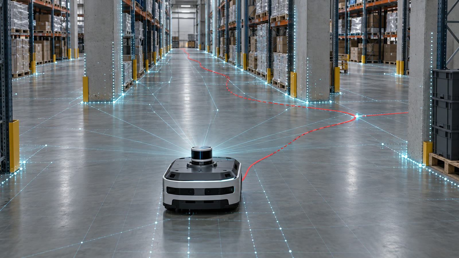
    Featured image: AI-generated editorial illustration of lidar mapping, accumulated path drift, and loop closure in a warehouse, not a test of a specific robot.

    Primary and authoritative sources

  • Collaborative Robot Safety Belongs to the Application, Not the Arm

    Collaborative Robot Safety Belongs to the Application, Not the Arm

    A collaborative robot is often marketed as a machine that can work beside people without a fence. That description is useful, but incomplete. A robot arm may include force limits, monitored stops, and safety-rated controls, yet the arm is only one part of the finished application.

    The gripper, workpiece, fixtures, nearby machines, programmed path, speed, and human task can turn a low-energy robot into a hazardous system. A sharp tool can cut. A heavy part can fall. A slow arm can trap a hand against a rigid surface. Safe collaboration therefore belongs to the complete application, not to a product label.

    Collaboration describes an operating situation

    The International Organization for Standardization explains that collaborative robotics means people and automatically operated robot systems share a workspace. Its guidance on collaborative robot systems explicitly describes collaboration as a system or application rather than a particular type or brand of robot.

    This distinction changes the first engineering question. Instead of asking whether a robot is a 鈥渃obot,鈥?an integrator should ask which tasks bring a person into the robot’s operating space, what can happen during those tasks, and which safeguards control the resulting risks.

    A system can also change modes. It may run quickly behind guarding during automatic production, slow down when a person approaches, and enter a monitored stop while an operator loads a part. Calling the entire installation fenced or fenceless misses how safety functions are combined.

    ISO 10218 covers robots and their integration

    ISO published updated industrial robot safety standards in 2025. ISO 10218-1 addresses industrial robots, while ISO 10218-2 addresses industrial robot applications and robot cells. The split reflects an important ownership boundary: a manufacturer can design safety functions into the arm, but the integrator determines how the arm, tool, process, and workplace behave together.

    The standards use risk reduction rather than a promise of zero danger. Hazards are identified, risks are estimated, and controls are selected and verified. Protective measures can include inherently safer design, fixed or interlocked guards, presence sensing, safe speed limits, emergency stops, and instructions for use.

    OSHA’s robotics overview notes that many robot accidents occur during non-routine work such as programming, maintenance, testing, setup, or adjustment. These situations matter because workers may enter the operating envelope while normal production safeguards are changed or bypassed.

    Four collaboration techniques solve different problems

    ISO’s collaborative-robot guidance describes four commonly used techniques. A safety-rated monitored stop stops robot motion while a person is in the collaborative workspace. Hand guiding allows an operator to command motion through a suitable control device. Speed and separation monitoring adjusts or stops motion as distance closes. Power and force limiting controls energy and contact forces.

    These techniques are not interchangeable. A monitored stop is useful when a person loads a stationary process, but it does not permit the robot to keep moving beside that person. Speed and separation monitoring depends on reliable detection, stopping performance, and a layout that gives the robot enough distance to react. Power and force limiting may allow contact, but only after foreseeable contacts and trapping points have been evaluated.

    Several techniques can appear in one cell. The correct combination follows from the task and risk assessment rather than from a preference for one sensor.

    The end effector often controls the real hazard

    A rounded, lightweight arm may carry a sharp screwdriver, hot welding tool, vacuum gripper, or heavy metal component. The energy delivered by the application includes the tool and payload, not just the robot’s published force limit.

    Fixtures create additional risks. A moving arm that would cause a minor contact in open space can produce a crushing injury when a body part is trapped between the tool and a table, column, or machine. Integrators need to examine intended contacts, unintended contacts, and reasonably foreseeable misuse throughout the work area.

    The same system-level thinking appears in our article on robot actuator specifications: a peak component number does not describe the complete machine under sustained operation.

    Force and pressure require measurement

    ISO/TS 15066 supplements the industrial robot standards with guidance for collaborative systems, including biomechanical limits and considerations for different body regions. ISO/PAS 5672:2023 adds test methods for measuring forces and pressures in human-robot contacts.

    Configuration values alone are not enough. Contact behavior depends on speed, effective moving mass, tool geometry, control response, stopping time, and whether the contact is transient or creates clamping. Verification uses suitable measurement equipment at representative contact points and operating conditions.

    Changes can invalidate an earlier result. A heavier gripper, faster program, different workpiece, moved table, or updated safety setting can alter the risk. Safety validation needs change control, not a one-time certificate stored after commissioning.

    Separation monitoring needs a stopping-distance budget

    A scanner or vision system does not stop a robot instantly. Detection takes time, the safety controller processes the event, drives react, and the mechanism decelerates. The person can continue moving during the same interval.

    A protective separation distance must account for approach speed, response time, measured stopping time and distance, sensor uncertainty, and possible intrusion around or above the detection field. Payload, pose, temperature, and wear can change stopping performance.

    This resembles the engineering behind minimal-risk stops in automated vehicles: detecting a problem is only the first step; the system must still reach a safe state within real physical limits.

    Maintenance and teaching deserve their own analysis

    Production mode may be highly automated and well protected, while troubleshooting requires a technician near the tool with power available. Teaching can involve repeated low-speed motion, attention focused on a pendant, and temporary fixtures. Cleaning and jam recovery can expose stored pneumatic, hydraulic, electrical, or gravitational energy.

    OSHA lists machine guarding and control of hazardous energy among the relevant protections for robot workplaces. A collaborative operating mode does not replace lockout procedures when a task requires hazardous energy to be isolated.

    Training must match roles. An operator, programmer, maintenance technician, and integrator need different knowledge and authority. Access to safety configuration should be controlled so ordinary program edits cannot silently weaken validated limits.

    How to evaluate a collaborative robot proposal

    Ask the supplier to describe the complete application, not only the arm. Request the task-based risk assessment, safety-function architecture, stopping measurements, force and pressure test plan, tool and payload assumptions, and validation records. Confirm how maintenance, teaching, startup, and foreseeable failures are handled.

    Look for clear ownership of later changes. A cell that is safe with one lightweight plastic part may need new testing before it handles metal components. Production targets should be evaluated with safety enabled; a demonstration that reaches its promised cycle time only after limits are relaxed is not a credible design.

    Limitations and what to watch next

    Standards provide a framework, but they cannot list every tool, process, body position, or misuse. Biomechanical data also continue to evolve, and ISO has begun work to revise the collaborative-contact guidance. Non-industrial service and humanoid robots may require different standards even when some principles transfer.

    Watch for better contact-test methods, validated human-detection systems, automatic configuration checking, and clearer change-management tools. The most useful progress will make safe integration easier to verify without pretending that a robot becomes harmless because its controller displays a collaborative mode.

    A cobot can be an important building block. Safety emerges only when the entire task, workplace, and life cycle are engineered and tested around the people who will actually use it.

    Primary and authoritative sources

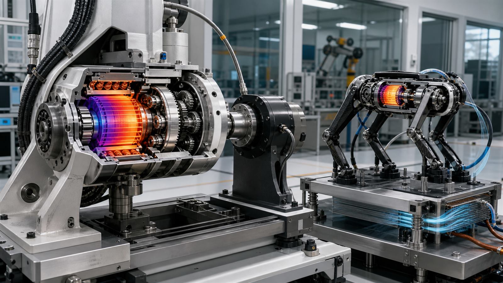
  • Robot Actuators Need Thermal Data, Not Just Peak Torque

    Robot Actuators Need Thermal Data, Not Just Peak Torque

    A robot joint specification can make peak torque look like the decisive number. It is easy to compare, sounds powerful, and helps produce an impressive jump or lift in a short demonstration. Yet peak torque says little about how long the joint can sustain a load, how quickly it can move, how much heat it generates, or what happens when the robot collides with the world.

    Actuator design is a system tradeoff among the electric motor, gearbox, bearings, sensors, power electronics, cooling, structure, and controller. A useful specification needs to describe that complete joint under a realistic duty cycle. Otherwise, the largest number on the page may represent only a burst that lasts until a thermal limit intervenes.

    Peak torque and continuous torque answer different questions

    An electric motor produces torque in proportion to current over much of its operating range. More current can create a short burst of force, but resistive heating rises approximately with the square of current. Windings, magnets, insulation, bearings, and electronics all have temperature limits.

    Peak torque is therefore a short-duration capability defined by starting temperature, current limit, voltage, cooling, and allowed time. Continuous torque is the level the actuator can maintain once heat generation and heat removal approach equilibrium. Neither number is meaningful without its test conditions.

    A peer-reviewed quasi-direct-drive exoskeleton study illustrates the distinction clearly. Its actuator produced a reported nominal torque of 17.5 newton-meters and a peak near 42 newton-meters under different currents, while the researchers separately measured stator and housing temperatures during sustained operation. The result is specific to that design and test, but the measurement method is the important lesson.

    A duty cycle turns a burst into an engineering requirement

    A humanoid standing still, a quadruped climbing stairs, and a robot arm repeating a pick-and-place motion impose different thermal loads. A joint may deliver high torque for one second, recover during a swing phase, and remain within limits. The same joint could overheat while holding a heavy object at arm’s length.

    Engineers therefore use time histories rather than one load point. They examine root-mean-square current, joint speed, regeneration, ambient temperature, airflow, contact with heat-spreading structures, and how neighboring actuators warm one another. A published continuous rating should state the cooling arrangement and temperature criterion, while a peak rating should include duration and recovery time.

    This matters especially for humanoid robots expected to work for long shifts. A brief athletic demonstration does not establish repetitive-work endurance.

    Gear reduction exchanges speed for torque

    A gearbox lets a fast motor produce more output torque at a lower joint speed. Increasing the reduction ratio can make a smaller motor lift a larger load, but it also changes reflected inertia, friction, backlash, efficiency, and how easily external forces move the joint.

    High-ratio transmissions suit accurate position control and slow heavy tasks. They can also make contact feel rigid and hide output torque behind uncertain friction. Low-ratio, or quasi-direct-drive, systems use motors with greater torque density and less reduction. They tend to be easier to backdrive and can estimate joint torque more directly from motor current, but the motor and electronics may be larger and thermally demanding.

    There is no universally superior ratio. A gripper finger, a warehouse arm, a walking knee, and a mobile robot wheel occupy different regions of the torque-speed map.

    Backdrivability changes how a robot handles contact

    A backdrivable joint can be moved from its output side with relatively little force. That property lets a leg yield during impact, helps a person guide an arm by hand, and reduces the apparent mechanical impedance presented to the environment. It is not the same as being intrinsically safe, because mass, speed, control faults, sharp tools, and stored energy still matter.

    The original MIT Cheetah actuator research treated torque density, efficiency, force-control bandwidth, and impact mitigation as connected design goals. The researchers used low reduction and low leg inertia to improve backdrivability while retaining high-bandwidth control. Their impact-mitigation metric also showed why a transmission cannot be evaluated by static torque alone.

    Series elastic actuators take another route by placing a spring in the force path. Spring deflection provides a force measurement and mechanical compliance, but adds travel, resonance, packaging, and control considerations. Software-controlled compliance cannot simply erase the inertia and friction of the hardware beneath it.

    Torque density must include the whole joint

    Motor torque divided by motor mass can be useful when comparing similar electromagnetic designs. A robot carries more than a motor, however. The gearbox, housing, bearings, encoder, brake, cables, inverter, cooling hardware, and structural interfaces all contribute mass and volume.

    Where that mass sits matters. Weight near a robot’s body is easier to accelerate than the same weight near a foot or hand. Designers sometimes use remote motors with belts, tendons, or linkages, accepting complexity to reduce limb inertia.

    Our article on robot hands and tactile sensing describes a similar integration problem: adding sensing and dexterity is valuable only if mass, wiring, durability, and calibration remain manageable.

    Speed, bandwidth, and torque cannot all peak together

    An actuator has a torque-speed envelope, not one operating point. Voltage limits maximum motor speed, current limits torque, and available electrical power constrains combinations of both. Gear losses and motor efficiency vary across the map.

    Control bandwidth adds another dimension. A joint may produce large static torque but respond too slowly for stable foot contact or force control. Sensor filtering, communication delay, inverter update rate, structural resonance, and gearbox compliance can all limit the closed-loop response.

    A 2024 two-speed robotic actuator study explored one response to conflicting requirements: changing effective gear ratio so the mechanism can support high force in one mode and higher speed with better backdrivability in another. The proof of concept also highlights the extra mechanisms and control needed to shift without losing authority.

    Bench tests need wear and repeated impacts

    Fresh gears and bearings do not describe lifetime performance. Backlash can grow, lubricant can change, cable strain relief can fail, seals add friction, and repeated shock loads can damage teeth or bearings. Thermal cycling can loosen interfaces and alter sensor offsets.

    An open-source legged-actuator study reported electrical, mechanical, thermal, and wear characterization, including hundreds of thousands of gait cycles. The specific design is not a universal benchmark, but publishing the test history makes the result far more useful than a peak specification without endurance evidence.

    For precise industrial work, wear also affects calibration. Our comparison of robot accuracy and repeatability explains why a machine can return consistently to the wrong physical location as loads and geometry change.

    Power electronics and batteries set system limits

    Multiple joints can request peak current simultaneously during a jump, recovery step, or heavy lift. The battery, DC bus, connectors, inverters, and protection system must survive that combined demand. Regenerative braking can return energy, but only when the bus and battery can accept it.

    Thermal derating should be coordinated with motion planning. If one knee approaches its limit, the robot may redistribute load, slow the task, change posture, or stop safely. A controller that assumes the advertised peak is always available can generate commands the hardware cannot deliver.

    How to read an actuator specification

    Look for continuous and peak torque with durations, joint speed at those loads, full actuator mass, gear ratio, backlash, efficiency, reflected inertia, backdrive torque, torque-control bandwidth, sensor method, cooling conditions, ambient temperature, ingress protection, and expected service life.

    Then ask for the duty cycle used to validate the joint. A useful report should show temperature over time, electrical power, repeated-cycle performance, impact loads, and any software derating. For a complete robot, check whether ratings apply to one isolated actuator or all joints operating together.

    What to watch next

    Better magnetic materials, winding methods, power semiconductors, compact cooling, integrated torque sensing, variable transmissions, and co-design software will keep improving robot joints. The more important market change will be standardized reporting that makes sustained work, contact behavior, and durability comparable across machines.

    Peak torque will remain useful, but it should be the start of a question rather than the end of one. Robots become practical when their actuators deliver the required force, speed, compliance, and uptime together.

    Primary and authoritative sources

  • Robot Accuracy and Repeatability Are Different Engineering Problems

    Robot Accuracy and Repeatability Are Different Engineering Problems

    An industrial robot can return to almost the same point all day and still be consistently wrong about where that point is. That is the difference between repeatability and accuracy. Repeatability describes how closely repeated motions agree with one another. Accuracy describes how closely the actual tool position matches the commanded position in a defined coordinate system.

    The distinction is easy to miss because many factory applications are taught by physically moving the robot to each required pose. If the robot repeats those taught poses, a small offset from an abstract coordinate does not matter. Newer workflows are less forgiving. Offline programming, machine tending, multi-robot assembly, large-part inspection, and vision-guided work all depend on coordinate frames that must agree with the real cell.

    Repeatability and accuracy answer different questions

    Suppose a controller commands the robot’s tool center point to the same location ten times. If all ten measured positions form a tight group, the robot is repeatable. If the center of that group is several millimeters from the commanded location, it is not accurate. Calibration can move the group toward the target, but it cannot remove random spread or mechanical instability.

    The reverse is also possible in a limited test: the average of several positions may be close to the target while individual attempts scatter too widely for the process. A useful performance description therefore needs both bias and variation. One number cannot explain the complete behavior.

    ISO 9283 defines performance criteria and related test methods for manipulating industrial robots. Its continuing relevance is a reminder that pose accuracy, pose repeatability, path behavior, overshoot, drift, speed, and other characteristics must be measured under declared conditions rather than blended into a single marketing claim.

    Why factories often prioritize repeatability

    Traditional robot deployment relies heavily on teach-in programming. An integrator places a gripper, welding torch, or dispenser at the desired physical pose and saves the robot’s joint coordinates. The controller does not need a perfect global model if it can return to that same pose reliably. Fixtures and guide features can absorb small offsets.

    This approach is practical for a stable task, but it becomes expensive when a cell changes. Moving the robot base, replacing a tool, repairing a joint, altering a fixture, or importing an offline program can invalidate taught points. Engineers then spend time touching up positions. A robot with better absolute accuracy can transfer programs and geometry with less manual correction, although the rest of the cell must be calibrated as well.

    A robot cell contains many coordinate systems

    The controller estimates tool position from joint encoder readings and a kinematic model of link lengths, joint axes, and mechanical offsets. The resulting pose is expressed relative to the robot base. A real application adds a tool frame, workpiece frame, camera frame, conveyor frame, external axis, and sometimes another robot’s frame.

    Each transformation introduces uncertainty. A precisely calibrated arm can still miss if the tool center point was measured poorly or a fixture moved. A camera may locate an object accurately in pixels while the camera-to-robot transformation is wrong. This is why the US National Institute of Standards and Technology develops calibration and registration tools for robot users rather than treating calibration as one hidden factory setting.

    Registration connects coordinate systems. The robot must know where a sensor, workpiece, or second machine sits relative to itself. NIST research on an augmented-reality interface for robot-sensor registration emphasizes that the quality and distribution of measured points affect the resulting transformation. Collecting many nearly identical points can produce weaker geometry than a well-distributed set across the useful workspace.

    Where positioning errors come from

    Manufacturing tolerances create small differences in link dimensions and joint alignment. Gear backlash, compliance, bearing behavior, encoder offsets, and controller models add more error. A long arm magnifies angular errors at the tool. Payload can bend links and mounts, while acceleration can produce dynamic deflection that a slow calibration does not capture.

    Temperature matters because structures and transmissions expand, lubricants change behavior, and electronics drift. Wear, collisions, maintenance, and remounting can alter a robot that was accurate when first installed. Cables and hoses can apply pose-dependent forces. The workpiece and tooling may also move, so an apparent robot error can originate elsewhere.

    These effects are configuration-dependent. A compensation model built from points in one corner of the workspace may perform poorly near full extension or with a different payload. Validation needs to cover the region, orientations, speeds, loads, and approach directions used by the actual process.

    Calibration builds a better model from external measurements

    A typical calibration procedure moves the robot through a set of poses while an external system measures the true position, and sometimes orientation, of a target attached to the tool. Software estimates model parameters that reduce the difference between measured and predicted poses. The updated model can compensate for geometric offsets and, in more advanced systems, some compliance or thermal effects.

    Laser trackers are common in large workspaces because they can follow a retroreflector with high precision. Photogrammetry, coordinate-measuring systems, cameras, articulated measurement arms, and dedicated calibration artifacts serve other needs. NIST has demonstrated external laser-tracker guidance for a large industrial robot, illustrating how metrology can close the gap between repeatable motion and demanding absolute positioning.

    The measuring system is not perfect ground truth. It has its own calibration, line-of-sight limits, environmental sensitivity, target offsets, timing behavior, and uncertainty. A credible calibration report identifies the reference equipment, traceability, measurement volume, robot configuration, data excluded, model fitted, and independent validation points.

    Calibration cannot repair every weakness

    Model correction is most effective against repeatable systematic error. It cannot make loose joints rigid, eliminate random encoder noise, restore a damaged gearbox, or prevent an unstable fixture from moving. If repeatability is poor, fitting a more elaborate accuracy model may simply chase variation in the calibration data.

    Nor is calibration permanent. A cell needs verification after collisions, major maintenance, base movement, tool replacement, or unexplained quality drift. The right interval depends on process tolerance, usage, environment, and the ability to detect change. A high-risk or high-value process may justify check artifacts or reference poses that operators can test routinely.

    This operational discipline complements repeatable robot agility tests. A laboratory benchmark establishes comparable performance, while cell-level verification shows whether the installed machine still meets the task.

    Applications differ in how much absolute accuracy they need

    Simple pick-and-place between fixed nests may rely mostly on repeatability. Robotic machining, drilling, measurement, and large-component assembly need stronger path and absolute accuracy. Multi-robot handoffs require both machines to agree on a shared frame. Digital twins and offline programs are only useful when virtual geometry maps reliably to physical equipment.

    Vision can correct some errors by measuring the workpiece close to the task, but it introduces camera calibration, lighting, occlusion, and latency. Force sensing can guide insertion, but it does not make a poor geometric model disappear. Our articles on tactile robot hands and robot-learning data quality show the same pattern: better sensors and models help only when their coordinate frames, timing, and calibration are trustworthy.

    What buyers should ask for

    A useful robot proposal should state which accuracy and repeatability metric is quoted, the test standard, payload, speed, warm-up, workspace location, tool configuration, environmental conditions, and uncertainty. Buyers should ask whether the value describes the bare robot, a calibrated option, or the complete installed process.

    They should also ask how programs transfer after maintenance, how tools and work frames are registered, what equipment verifies the cell, and which changes trigger recalibration. Acceptance testing should use representative paths and loads, not only a convenient pose near the center of the workspace.

    What to watch next

    Improved factory metrology will make calibration faster and easier to repeat. Watch for automated reference targets, continuous health checks, compensation that accounts for payload and temperature, better uncertainty reporting, and portable methods small manufacturers can use without a specialist laboratory.

    The most important shift is conceptual. Repeatability says a robot can make the same motion again. Accuracy says the motion agrees with the outside world. Flexible automation needs both, plus a calibrated chain connecting robot, tool, sensor, workpiece, and task.

    Primary and authoritative sources

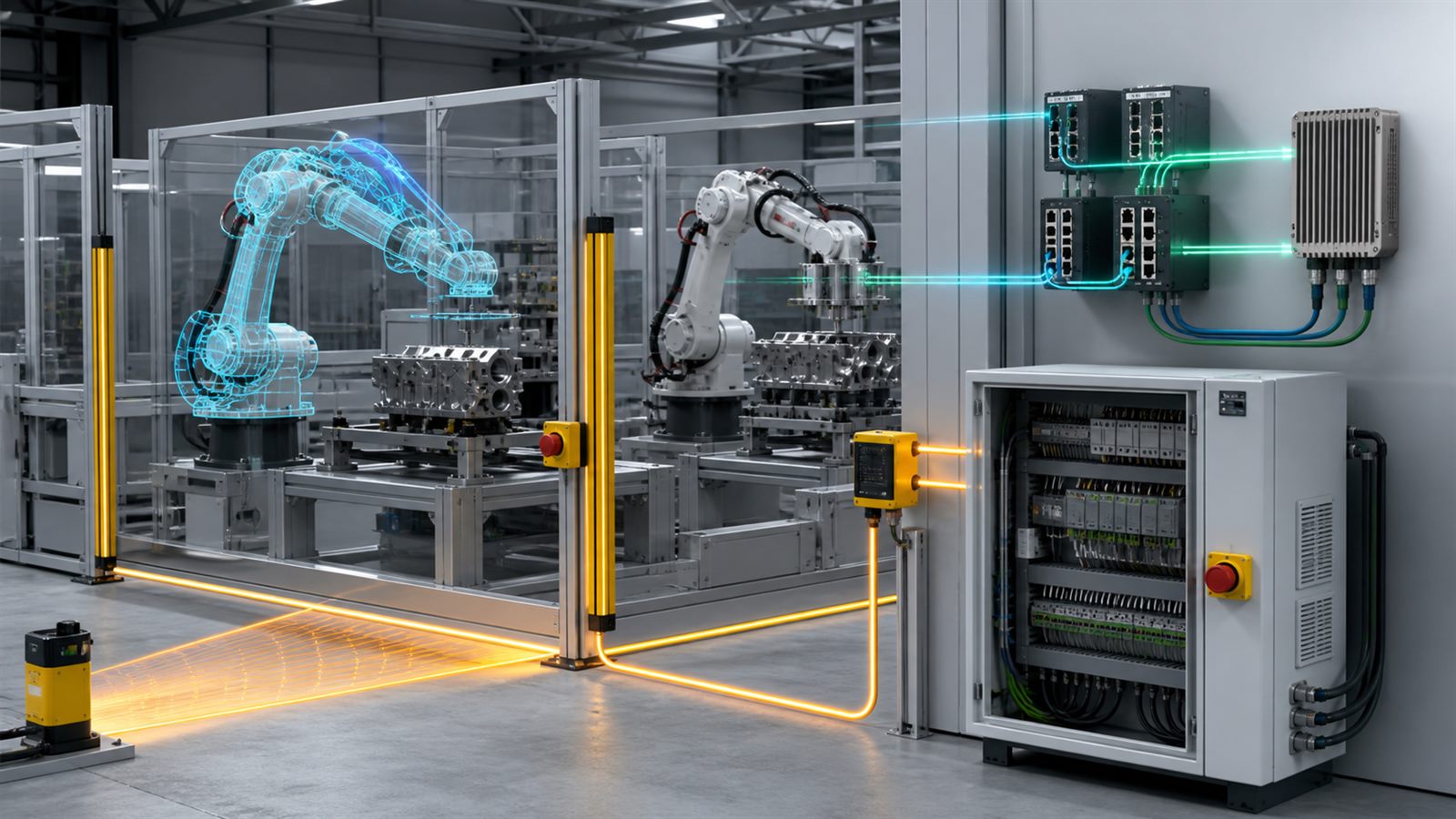
  • Robot Cybersecurity Has to Preserve Physical Safety and Uptime

    Robot Cybersecurity Has to Preserve Physical Safety and Uptime

    An industrial robot is both a computer system and a machine that moves with force. Its controller receives programs, reads sensors, drives motors, coordinates tools, and exchanges data with production systems. A cybersecurity failure can therefore affect more than confidential information: it can change motion, stop production, damage work, or undermine assumptions used by safety systems.

    Industrial automation has strict timing, availability, recovery, and physical-safety requirements. Robot security must be engineered across the product, integrator, factory network, safety architecture, maintenance process, and incident response plan.

    A robot cell contains more than a robot arm

    A typical cell can include a robot controller, drives, programmable logic controller, safety PLC, vision system, end effector, sensors, human-machine interface, industrial switches, engineering workstation, and connections to manufacturing software. Vendors and integrators may provide different pieces.

    Each component has firmware, configuration, identities, communication protocols, and a support lifecycle. A welding robot, packaging arm, mobile manipulator, and laboratory robot create different consequences if a command is delayed or changed.

    Cyber risk becomes physical through control

    An attacker or accidental change could alter a program, tool frame, speed limit, calibration value, safety-zone configuration, or production recipe. A denial-of-service event may halt a line, while false sensor data can make equipment respond to a condition that does not exist.

    Silent changes to quality parameters can create defective products, and corrupted logs can hide the cause. Security planning should consider safety, product integrity, equipment damage, downtime, and recovery evidence alongside data theft.

    Safety functions and cybersecurity have different jobs

    Machine safety reduces risk from foreseeable hazards using guards, interlocks, scanners, emergency stops, safe speed limits, and validated control functions. Cybersecurity reduces the chance that unauthorized or corrupted actions reach the system. Neither discipline replaces the other.

    A safety function should not depend entirely on an ordinary business network or cloud service. At the same time, a safety controller still has configuration and lifecycle risks. The boundary between standard control and safety control must be documented so a security change does not weaken a validated protective function.

    Availability changes the defensive design

    Office systems can often reboot, scan files aggressively, or isolate a device when suspicious behavior appears. Stopping industrial equipment without understanding its state can trap material, damage tooling, interrupt cooling, or create a difficult restart. Some legacy controllers cannot run endpoint agents.

    NIST’s operational-technology guidance emphasizes performance, reliability, and safety alongside security. Controls should be tested against robot cycle time and failure behavior. A monitoring tool that overloads a controller or blocks deterministic traffic can create the operational problem it was meant to prevent.

    Asset inventory is the starting point

    A factory cannot protect a controller, engineering laptop, remote gateway, or unmanaged switch it does not know exists. The inventory should record model, firmware, network location, owner, supported protocols, safety role, dependencies, backups, remote-access path, and vendor support status.

    Logical diagrams need physical context. A network device connected to a packaging robot carries a different risk from one connected to a test bench. Mapping assets to cells and processes helps teams prioritize controls and plan maintenance windows.

    Segmentation limits how far a failure can travel

    Robot cells should not share unrestricted connectivity with office computers or every production device. Segmented zones and controlled conduits can limit communication to required paths. Industrial firewalls and monitored gateways reduce exposure.

    Segmentation must reflect real operations. Engineers may need recipe downloads, diagnostics, historian data, and vendor support. Blocking undocumented traffic before understanding it can interrupt production, so teams should observe, document, test, and phase changes.

    Remote access needs explicit ownership

    Remote diagnostics can reduce downtime, especially when a specialized integrator supports the cell. It can also create an entry point that remains forgotten after commissioning. Shared accounts, always-on tunnels, and unmanaged vendor laptops weaken accountability.

    Access should be approved, time-limited where practical, authenticated, logged, and limited to the necessary system. The site needs a reliable way to disable remote connectivity without disabling local safety or losing the evidence needed for investigation.

    Software integrity starts before installation

    Robot programs, controller firmware, libraries, vision models, and configuration packages should have known sources and controlled versions. Digital signatures and integrity checks can help detect unauthorized changes. Application allowlisting can prevent unknown software from running on compatible workstations and servers.

    Provenance is useful but limited. As our article on software build provenance explains, knowing how an artifact was produced does not prove it is free of vulnerabilities. Secure development, testing, defect handling, patch management, and end-of-life planning remain necessary.

    Patching needs a robot-specific test path

    A security update may change timing, drivers, certificates, or controller behavior. Installing it directly on production can create risk; delaying indefinitely leaves known weaknesses. A credible process evaluates severity, exposure, compensating controls, vendor guidance, and downtime.

    Updates should be tested on representative equipment or a controlled staging environment, with backups and a rollback plan. After installation, teams should verify safety functions, calibration, network communication, cycle performance, and quality output rather than checking only that the controller restarted.

    Behavioral monitoring should understand physics

    Network monitoring can reveal unexpected connections, protocols, or data rates without installing software on every controller. File-integrity monitoring can flag changed programs. Physical process monitoring can compare commanded motion, sensor readings, energy use, and cycle timing with expected behavior.

    NIST has demonstrated behavioral anomaly detection in a robotics-based manufacturing environment. An alert is still evidence for investigation, not proof of an attack. Tool wear, maintenance, new products, and legitimate program changes can also shift behavior. A digital twin may help organize expected states, but it must be validated and protected from bad inputs.

    The integrator owns important safety-security connections

    ISO 10218-2:2025 addresses industrial robot application integration across design, commissioning, operation, maintenance, and decommissioning. Cybersecurity standards such as IEC 62443 address secure product development and automation-system security processes. Applying both perspectives exposes gaps that one supplier cannot solve alone.

    The robot maker controls the base product, the integrator designs the application, and the factory operates the result. Contracts and documentation should identify who manages accounts, certificates, patches, backups, remote support, vulnerability notices, and safe recovery throughout the cell’s life.

    Recovery must restore a known physical state

    A backup is only useful if it includes the correct programs, safety configurations, calibration data, recipes, controller settings, and dependencies. Restoration should occur into a controlled environment, followed by integrity checks and staged recommissioning.

    NIST’s 2026 manufacturing response-and-recovery work emphasizes operational resilience in industrial control environments. For robots, recovery is not finished when files return. Guards, interlocks, coordinate frames, tools, payload settings, and process quality must be verified before normal production resumes.

    Incident exercises should include operations and safety teams

    A cyber response plan written only by IT may assume a device can be unplugged immediately. A joint exercise can define who can stop a cell, how to stabilize equipment, which logs to retain, and how to communicate with vendors.

    The exercise should include a safe restart, not just containment. Lessons from robot safety standards for shared workspaces and mobile-robot safety remain relevant because people interact with the system during maintenance and recovery.

    Limitations

    Industrial robot architectures vary widely, and controls suitable for a new Ethernet-connected cell may not fit isolated legacy equipment. Standards define processes and requirements but do not certify that a particular deployment is secure. NIST reference architectures are examples, not universal product endorsements.

    Security monitoring can produce false positives, and aggressive isolation can create operational hazards. Digital twins cannot detect every attack, especially when models or reference data are compromised. Risk decisions require the robot manufacturer, integrator, owner, safety specialists, and cybersecurity team.

    What to watch next

    Watch for robot vendors adopting secure development and signed-update practices, clearer vulnerability support periods, tested asset inventories, interoperable security logs, cell-level recovery exercises, and safety validation after patches. The evolution of NIST OT guidance and the IEC 62443 series should make connected automation responsibilities more explicit.

    A secure robot is not merely one that rejects unauthorized logins. It is a system that preserves trustworthy motion, safe boundaries, product integrity, and recoverable operation through years of software and production change.

    Sources: NIST SP 800-82 Revision 3, Guide to Operational Technology Security; NIST SP 1800-10, Protecting Information and System Integrity in Industrial Control System Environments; NIST SP 1800-41 manufacturing response and recovery draft; ISO 10218-2:2025, safety requirements for industrial robot applications and cells; IEC 62443-4-1 secure product development lifecycle requirements.

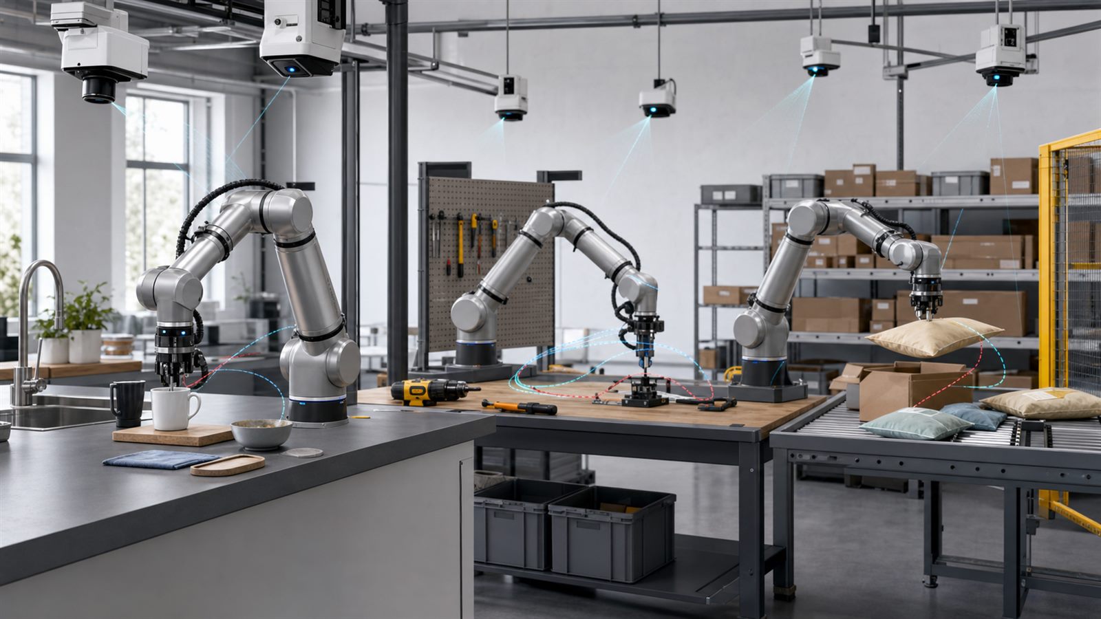
  • Robot Learning Needs Diverse Data, Not Just More Demonstrations

    Robot Learning Needs Diverse Data, Not Just More Demonstrations

    A robot cannot learn physical work from the open web in the same way a language model learns from pages of text. Useful manipulation data must connect camera images and sensor readings to precisely timed actions on real hardware. Someone has to operate the robot, arrange the scene, recover from mistakes, check the recording, and often repeat the task under different conditions.

    That makes robot demonstrations expensive, but expense is only part of the challenge. A million nearly identical motions can teach a narrow habit. A smaller collection with varied objects, lighting, viewpoints, operators, failures, and environments may provide more useful evidence about how a policy will behave outside the laboratory.

    A robot demonstration is a synchronized episode

    A training episode typically contains a sequence of observations and actions. Observations may include fixed-camera images, wrist-camera images, depth, joint positions, gripper state, force, and tactile signals. Actions describe how the robot moved, while a language instruction or task label explains the intended goal.

    These streams need accurate timing and calibration. If an action is paired with the wrong video frame, the model learns a distorted relationship between what it sees and what the robot did. Missing camera geometry, inconsistent units, or an undocumented controller can make data difficult to reuse on another system.

    Repetition and diversity solve different problems

    Repeated demonstrations help a model estimate a task reliably and capture natural variation in human control. Diversity determines whether that skill survives a change in cup shape, table height, clutter, lighting, camera position, or background. Both matter, but one cannot fully replace the other.

    A dataset should describe its distribution rather than advertise only an episode count. Buyers and researchers need to know which tasks dominate, how many distinct scenes and objects are represented, how often attempts fail, and whether the evaluation environment resembles the training environments.

    Open X-Embodiment showed the value of a common format

    The Open X-Embodiment collaboration assembled datasets from 22 different robots across 21 institutions and represented them in a shared episode format. Its RT-X experiments provided evidence that training across robots can produce positive transfer, allowing experience from multiple platforms to improve policies on individual systems.

    A common container is not the same as identical data. Different robots have different joints, cameras, grippers, action spaces, control rates, and task conventions. Standardization makes comparison and co-training possible, but models still need explicit mappings between embodiments and careful treatment of missing sensors.

    DROID traded hardware variety for scene variety

    The DROID project used a shared robot hardware setup across many institutions to collect about 76,000 demonstration trajectories, representing roughly 350 hours of interaction across hundreds of scenes. Keeping the arm, cameras, and control stack consistent reduced one source of variation while allowing collectors to move the system through laboratories, offices, and homes.

    That design illustrates an important choice. A cross-robot dataset explores hardware diversity; a shared-platform dataset can concentrate on objects, tasks, operators, and environments. Neither is universally better. The right mixture depends on whether the target is one deployed robot family or a policy meant to adapt across many bodies.

    Calibration and metadata are part of the training signal

    Camera calibration connects pixels to physical geometry. Robot configuration identifies joint limits, gripper behavior, coordinate frames, and controller assumptions. Metadata about scene, operator, success, task, and collection software makes it possible to filter episodes and diagnose bias.

    The DROID maintainers later published improved camera calibrations for tens of thousands of episodes and expanded language annotations for successful episodes. That is a reminder that datasets are maintained technical products. Versioning, correction records, licenses, and checksums matter alongside the raw recordings.

    Successful demonstrations are not enough

    If a dataset contains only smooth successes, a policy receives little evidence about how failure begins or how to recover. Real deployments include slipping objects, blocked paths, unexpected contact, ambiguous instructions, and partial task completion. Negative examples and recovery demonstrations can help distinguish a minor deviation from a state that requires stopping.

    Failure data must be collected safely and labeled carefully. A robot should not be encouraged to explore dangerous contact around people or fragile equipment simply to increase variety. Safety limits, simulation, controlled perturbations, and human supervision define what can be recorded responsibly.

    Language labels can hide disagreement

    Vision-language-action models connect instructions such as placing an object in a container to continuous robot actions. Natural language makes a policy easier to command, but labels can be vague. Two annotators may describe the same motion differently, while the same phrase may refer to several acceptable outcomes.

    Multiple descriptions, structured task metadata, and clear completion criteria can reduce that ambiguity. Language should complement sensor evidence rather than conceal a poorly specified task. This becomes especially important for robot foundation models that combine data from many sources.

    Touch data is valuable and difficult to combine

    Images reveal object appearance and approximate geometry, but they do not directly measure grip force, friction, softness, or whether an object has begun to slip. Tactile and force sensors can expose those hidden states, particularly for deformable items and close contact.

    Sensor designs vary widely, making touch data harder to standardize than RGB images. Calibration drift and wear also affect measurements. The challenge supports the argument that robot hands need better touch and better benchmarks, not only larger vision datasets.

    Target-domain demonstrations remain important

    Large general datasets can provide a useful starting policy, but a new deployment has its own camera placement, objects, workflows, and failure costs. The DROID project documentation recommends adding a small amount of teleoperated data from the target domain when training for that setting.

    This resembles adaptation in other machine-learning systems, but physical errors have immediate consequences. Local demonstrations should cover normal cases, edge cases, safe stops, and recovery states. They should also be separated carefully from evaluation data so a system is not tested on scenes it already saw during training.

    Evaluation needs to reveal the dataset’s boundaries

    A policy can score well when test tasks use familiar objects, backgrounds, or camera positions. Stronger evaluations change several factors independently and together. They measure task completion, unsafe contact, recovery, time, human intervention, and consistency across repeated trials.

    Physical tests should state the hardware, controller, environment, and statistical uncertainty. That complements our discussion of repeatable robot agility testing: a polished demonstration is evidence that one run worked, not a distribution of performance.

    Dataset governance will become deployment infrastructure

    Organizations need provenance for who collected data, which consent and workplace rules applied, what licenses permit, and whether cameras captured personal or confidential information. Access controls and retention policies matter when data comes from homes, hospitals, or factories.

    Documentation should also record dataset versions, known gaps, collection incentives, and filtering decisions. A robot policy may reproduce the habits and blind spots of its demonstrators, so collection teams and environments should be diverse enough to reveal systematic bias.

    Limitations

    Public robot datasets represent only part of the data used by commercial systems, so comparisons are incomplete. Results from one policy architecture may not transfer to another. Dataset size, task definitions, and success labels can also be counted differently, making headline numbers difficult to compare.

    More diverse data does not remove the need for mechanical reliability, safety engineering, runtime monitoring, and testing on the deployed system. A learned policy is one component of a robot, not the entire safety case.

    What to watch next

    Watch for richer open dataset cards, common episode schemas that preserve calibration and licensing, practical methods for learning from failures, better integration of touch and force, and benchmarks that hold out entire environments rather than random episodes. Tools that reduce the labor of teleoperation without degrading labels will also matter.

    Robot learning will benefit from more demonstrations, but scale is meaningful only when the recordings preserve the variety, context, and quality needed for machines to act reliably in a changing physical world.

    Sources: Open X-Embodiment: Robotic Learning Datasets and RT-X Models; Open X-Embodiment dataset repository; DROID: A Large-Scale In-The-Wild Robot Manipulation Dataset; DROID policy-learning and dataset documentation.

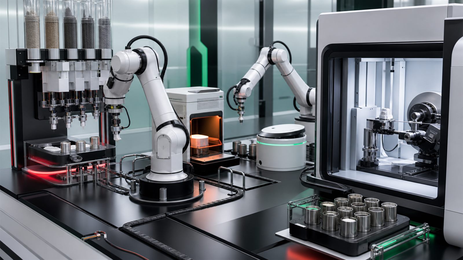
  • Self-Driving Laboratories Need Interoperable Instruments and Reproducible Data

    Self-Driving Laboratories Need Interoperable Instruments and Reproducible Data

    A self-driving laboratory is more than a robot arm beside an artificial-intelligence model. It is a closed experimental system that proposes a test, prepares a sample, controls instruments, records results, evaluates uncertainty, and chooses what to try next. If any link in that loop is fragile, the laboratory may produce data quickly without producing knowledge that another team can reproduce.

    That is why the next engineering challenge is interoperability. Scientific instruments were usually designed for expert human operators, often with proprietary control software and inconsistent data formats. Autonomous research requires those instruments, sample holders, algorithms, and data systems to communicate with enough precision that a result can be traced and repeated.

    What makes a laboratory self-driving

    Traditional automation repeats a fixed sequence. An autonomous laboratory adds decision-making: an algorithm uses previous measurements to select the next experiment according to an objective, such as finding a material with a target property or mapping a formulation’s phase behavior. Robotic equipment executes the choice, characterization instruments return measurements, and the loop continues.

    NIST’s Autonomous Formulation Lab illustrates the concept by linking AI-directed planning with robotic preparation and in-situ scattering and other measurements. Its stated goals include reproducible methods, data standards, and shareable datasets. Those less visible elements matter as much as the robot because they allow results to move beyond one custom installation.

    Instrument control is still fragmented

    Many laboratory instruments expose vendor-specific commands, file formats, and timing behavior. A human can adapt when an instrument reports an unexpected state. Software needs an explicit description of whether a command succeeded, which sample was measured, what calibration was active, and whether the result is complete.

    NIST says the transition from human-operated instruments to AI-controlled infrastructure has often relied on fragile integrations. Its standards program is considering instrument control and communication, sample management, data and knowledge management, and algorithm integration as connected problems. Protocols such as MQTT, SiLA, and EPICS offer useful foundations, but materials laboratories also need agreement about experimental meaning, not only message transport.

    Samples need identities and histories

    A digital command is useless if the physical sample cannot be identified reliably. Autonomous workflows must track source materials, preparation steps, container geometry, position, environmental exposure, and every transformation. When a robot transfers powder, mixes a liquid, or heats a specimen, the system needs to preserve provenance across that physical change.

    Sample holders complicate interoperability because one instrument may accept a thin film while another requires powder, a flow cell, or a battery device. A common identifier and machine-readable history can prevent a result from being attached to the wrong specimen. It also lets a later researcher understand whether two nominally identical samples actually followed the same process.

    AI-ready data must include context

    A measurement file alone is rarely enough to train a reliable model. The dataset needs units, instrument configuration, calibration records, processing steps, environmental conditions, uncertainty, and failed experiments. Otherwise, an optimizer may learn a pattern caused by equipment drift or an undocumented preprocessing choice.

    Negative and inconclusive results are particularly important. If only successful syntheses are stored, the model receives a distorted view of the search space. Machine-actionable metadata should therefore capture what was attempted, why it was selected, and how the outcome was judged. This is where reproducibility and AI performance become the same infrastructure problem.

    The A-Lab result shows both promise and caution

    A 2023 Nature paper described an autonomous laboratory for inorganic materials synthesis that combined literature-derived recipes, machine-learning interpretation, active learning, robotics, and automated X-ray diffraction. The system conducted 353 experiments over 17 days and reported successful synthesis of 36 of 57 target compounds under the study’s criteria.

    The numbers are evidence from one particular platform and materials domain, not a general speed limit for science. The paper also attracted discussion about how novelty and synthesis success should be interpreted. That debate reinforces a useful principle: automated measurements and model judgments still need transparent criteria and expert review. A closed loop can accelerate a mistake as efficiently as it accelerates a discovery.

    Algorithms need portable interfaces

    An optimization algorithm should ideally express a high-level request without being rewritten for every pump, furnace, or diffractometer. NIST compares the need with scientific modeling environments that present a common abstraction over different computational codes. For experiments, that could mean standardized descriptions of capabilities, constraints, actions, and results.

    Portability would also improve comparison. The same planner could be tested across multiple laboratories, and different planners could operate the same equipment under controlled conditions. This resembles the challenge of coordinating mixed robot fleets through shared interfaces, though laboratory work adds stricter scientific provenance and uncertainty requirements.

    Safety cannot be inferred from a successful run

    An autonomous system may handle heat, pressure, reactive chemicals, radiation sources, or delicate instruments. Safe operation requires hardware interlocks, bounded action spaces, collision prevention, ventilation monitoring, and a defined human stop procedure. The AI planner should not be able to override physical protections.

    Testing should include abnormal conditions: a blocked dispenser, a missing sample, a sensor that drifts, a network interruption, or an instrument that returns a partial file. Repeatable test methods, like those discussed for robot agility and reliability, reveal whether a system fails safely rather than merely completing a demonstration.

    Humans remain responsible for the scientific question

    Autonomy can search a defined space more consistently than a person can run thousands of routine iterations. Humans still choose meaningful objectives, decide what constraints are ethical and practical, inspect unexpected results, and connect measurements to theory. The best systems treat automation as a way to expand scientific attention, not remove scientific judgment.

    General-purpose robot models may eventually simplify manipulation and instrument use, but the limitations described in robot foundation models and physical AI remain relevant. Flexible behavior must be paired with calibrated uncertainty and deterministic safety controls.

    Limitations

    Self-driving labs are expensive to build, and integration effort can exceed the cost of the visible robots. A method that works with liquids may not transfer to brittle solids or biological samples. Proprietary interfaces can prevent full data capture, while automated analysis can conceal model assumptions from users.

    Reproducibility also requires more than publishing software. Other laboratories need compatible materials, calibration standards, environmental controls, and enough procedural detail to reconstruct the experiment. Standardization should preserve room for novel instruments rather than freezing one architecture too early.

    What to watch next

    Watch for common sample identifiers, open capability descriptions for instruments, standardized uncertainty metadata, portable optimization interfaces, and benchmark experiments that can be repeated across institutions. Procurement may become a major lever if research organizations require machine-readable control and exportable raw data from new instruments.

    The most important autonomous laboratory will not be the one with the most dramatic robot. It will be the one whose decisions, samples, measurements, and failures can be understood and reproduced somewhere else.

    Sources: NIST: Autonomous Laboratories; NIST: Standards for a Modular and Autonomous Laboratory Ecosystem; NIST Autonomous Formulation Lab; Nature: An autonomous laboratory for the accelerated synthesis of novel materials.

  • Warehouse Mobile Robots Need Safety Standards Before They Scale

    Warehouse Mobile Robots Need Safety Standards Before They Scale

    Autonomous mobile robots are becoming ordinary warehouse equipment. They move totes, carry shelves, deliver parts, and help logistics teams handle repetitive transport work. The technology can be useful, but safe deployment is not just a question of buying a robot with sensors. Mobile robots share space with people, forklifts, pallets, doors, charging stations, and other machines. That makes safety a systems problem.

    For ordinary technology readers, the key point is simple: a mobile robot is not safe merely because it stops in a demo. It must be evaluated in its specified operating environment, with the right loads, floor conditions, traffic rules, speeds, visibility limits, and human workflows. The practical future of warehouse robotics depends as much on standards and test methods as on autonomy software.

    Mobile robots are different from fixed robots

    Traditional industrial robots often work inside fenced cells or defined collaborative workspaces. Autonomous mobile robots move through changing environments. A warehouse aisle may contain shrink wrap, dust, reflections, temporary obstacles, open pallets, workers carrying boxes, or another robot crossing the same path. The robot’s sensors and software must interpret that changing scene while following site rules.

    This is why mobile robot safety cannot be reduced to one lidar sensor or one emergency stop button. The robot, payload, route design, traffic management system, worker training, maintenance procedure, and facility layout all matter. A robot that is safe in one aisle may be inappropriate in another if slopes, blind corners, loading practices, or pedestrian traffic differ.

    Standards give buyers a vocabulary

    Industrial mobile robot standards such as ANSI/RIA R15.08 and ISO 3691-4 help define safety expectations for different classes of mobile systems. They are not exciting in the way a robot demo is exciting, but they give manufacturers, integrators, and facility operators a shared vocabulary for risk assessment, operating environments, protective functions, and user responsibilities.

    NIST’s work on mobile robotics systems research and standard test methods is important for the same reason. Common performance metrics make it easier to compare robots across mobility, perception, manipulation, and safety-related behavior. Without repeatable tests, buyers risk evaluating robots by video clips, vendor claims, or narrow pilots that do not reflect daily operations.

    Safety starts before the robot arrives

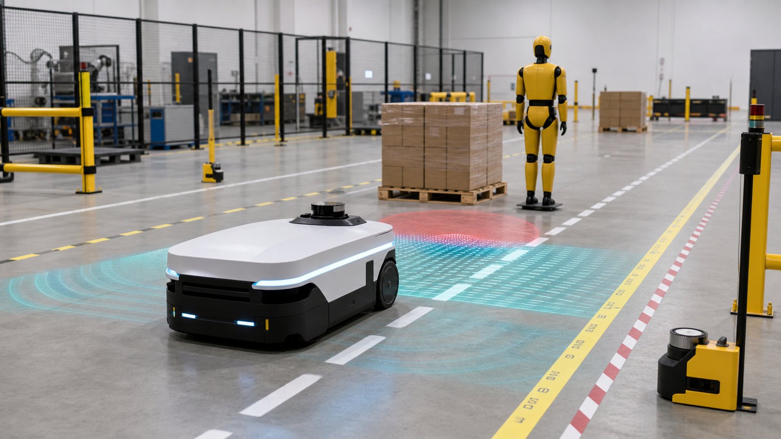
    A credible deployment begins with the workflow. What task will the robot perform? What route will it use? Who can enter that space? What happens if a pallet blocks the route? How fast can the robot move with and without a load? How will workers know whether a robot is yielding, rerouting, charging, or stopped? How are failures reported?

    Those questions sound procedural, but they determine whether autonomy helps or creates confusion. A warehouse can add robots faster than it updates training, signage, incident reporting, and traffic planning. That gap is where near misses can appear. The lessons are similar to those in Robot Agility Needs Repeatable Tests Before Buyers Can Trust the Demo: repeatable measurement matters more than impressive motion.

    Interoperability is a safety issue too

    Many facilities do not want to be locked into one robot vendor forever. They may use separate systems for picking, towing, inventory scanning, cleaning, and transport. If each fleet has its own map, traffic manager, status format, and operating assumptions, the site can become harder to manage. Interoperability work from groups such as MassRobotics aims to let autonomous mobile robots share basic information such as position, speed, direction, health, and task status.

    Interoperability does not solve safety by itself. A shared status format is not the same as a unified traffic-control system or a complete risk assessment. But it helps humans and software understand what mixed robot fleets are doing. That matters as warehouses move from isolated pilots to everyday multi-vendor automation.

    Limits buyers should not ignore

    Mobile robots can struggle with messy edge cases: hanging plastic, mirrors, low obstacles, unusual floor markings, clutter, damaged pallets, wireless dead zones, or people behaving unpredictably. A system may perform well during a vendor-supervised pilot and still need months of tuning before it is reliable in normal operations.

    Payloads also change risk. A small robot carrying light totes is different from a large mobile base carrying a heavy shelf or fitted with a robot arm. The robot’s braking distance, stability, center of gravity, sensor field of view, and safe speed all depend on the task. That connects to the tactile and manipulation questions raised in Robot Hands Need Better Touch, Not Just Better Vision. Mobility and manipulation become harder when robots physically interact with the world.

    What good deployment looks like

    A good deployment is boring in the right ways. Routes are mapped and reviewed. Workers understand robot behavior. Emergency stops and recovery procedures are tested. Speed limits match the environment. Near misses are recorded. Software updates are controlled. Charging areas do not create trip hazards. The operator knows which organization is responsible for maintenance, cybersecurity, and incident response.

    Cybersecurity also belongs in the safety discussion. A connected robot fleet depends on wireless networks, cloud dashboards, local controllers, and sometimes APIs connected to warehouse-management systems. Exposure management ideas like those in CTEM Turns Vulnerability Management Into Continuous Exposure Reduction apply to robotics because a software failure can become a physical operations problem.

    What to watch next

    Watch for more transparent test reports, clearer user responsibilities, mixed-fleet interoperability, and standards that keep pace with mobile manipulators and humanoid robots. Humanoid demos will get attention, but warehouse mobile robots are where many businesses will meet practical autonomy first.

    The durable robotics market will not be built on dramatic videos alone. It will be built on machines that can be evaluated, integrated, maintained, and operated safely in real workplaces. Standards are not the glamorous part of robotics, but they are what let automation scale without turning every deployment into an experiment.

    Sources: NIST Mobile Robotics Systems Research and Standard Test Methods; MassRobotics AMR Interoperability Standard overview; A3 presentation introducing R15.08 industrial mobile robot safety.

  • Robot Agility Needs Repeatable Tests Before Buyers Can Trust the Demo

    Robot Agility Needs Repeatable Tests Before Buyers Can Trust the Demo

    Robots are often judged by eye. A demo looks smooth, a humanoid recovers from a push, or a mobile robot drives through a warehouse aisle without stopping. Those moments are useful, but they are not enough for buyers who need to compare systems, plan deployments, and understand failure risk.

    Robot agility is becoming an engineering measurement problem. How quickly can a robot adapt to a changed route, uneven floor, unexpected obstacle, heavy payload, low battery, or degraded sensor? The answer needs repeatable tests, not only polished videos.

    Agility Means More Than Speed

    Speed is easy to measure, but agility is broader. A fast robot that stops for every small change may be less useful than a slower robot that handles real-world variation. Agility includes perception, planning, control, stability, recovery, and safe interaction with people and equipment.

    NIST has long worked on robotics and automation measurement science. That work matters because robotics markets need common ways to compare capabilities. Without shared tests, buyers are left with vendor claims that may not map to their own facilities.

    This is related to our earlier article on wearable robot standards. Whether the robot is worn by a worker or drives through a site, performance needs to be measured under defined conditions.

    Real Workplaces Are Full of Variation

    A robot in a lab may face clean floors, known lighting, predictable objects, and a patient test team. A robot in production faces dust, glare, reflections, damaged pallets, people taking shortcuts, temporary barriers, moved equipment, and imperfect Wi-Fi.

    Agility testing should expose systems to controlled versions of that variation. A mobile robot might be tested on ramps, gaps, cluttered paths, narrow passages, and changing layouts. A manipulation robot might be tested with objects that vary in shape, texture, weight, and position.

    The point is not to create impossible obstacle courses. The point is to learn where the robot’s competence ends. A clear boundary helps buyers deploy safely and helps developers improve the right parts of the system.

    Test Methods Need Repeatability

    For a test to be useful, it must be repeatable. Different teams should be able to set up similar conditions and compare results. That means defining the environment, objects, timing, scoring, allowed retries, safety rules, and what counts as failure.

    NIST’s emergency-response robot test methods are a useful reference point because they break complex performance into structured capabilities such as mobility, sensing, manipulation, and endurance. The same measurement logic can inform industrial and service robots, even when the exact tasks differ.

    Repeatability does not mean every deployment is identical. It means a test result has a clear meaning. If a robot completes a stair, ramp, or object-handling task, the setup should be documented well enough for another evaluator to understand the claim.

    Software Updates Complicate the Score

    Modern robots are software-defined systems. A navigation update can improve performance in one environment and create a regression in another. A new perception model can change how the robot reacts to edge cases. A fleet-management update can alter traffic behavior across many machines.

    That makes one-time certification insufficient for some deployments. Operators need change logs, regression tests, simulation results, and field monitoring. A robot that passed a test last year may need fresh evidence after a major update.

    This mirrors the issues in software updates for vehicles. When machines move through physical space, software changes become safety and operations changes.

    Simulation Helps but Cannot Replace Field Evidence

    Simulation is valuable because it can generate many scenarios quickly. Developers can test rare obstacles, lighting conditions, traffic patterns, and failure cases without putting people or equipment at risk. It is also useful for regression testing after software updates.

    But simulation depends on model fidelity. A virtual floor may not capture real friction, sensor noise, reflections, cable clutter, or human behavior. Therefore, simulation should be paired with physical tests and carefully selected field trials.

    The best testing stack uses several layers: simulation for breadth, laboratory test methods for repeatability, pilot deployments for realism, and ongoing monitoring for long-term drift.

    Safety and Productivity Should Be Measured Together

    A robot that is safe because it constantly stops may not be productive. A robot that is productive because it cuts margins too close may not be acceptable. Agility testing should therefore measure both task performance and safe behavior.

    Useful metrics can include completion time, intervention rate, near-miss events, blocked-path recovery, human wait time, energy use, payload handling, and failure mode. For fleet robots, congestion and coordination also matter. One robot can perform well alone while a fleet creates bottlenecks.

    That connects with mixed robot fleet interoperability. Agility is not only a property of one machine. It can be a property of the whole workflow.

    What Buyers Should Ask

    • Which standardized or repeatable tests has the robot completed?
    • What environmental limits were included, such as slope, lighting, floor condition, and obstacles?
    • How often does the system require human intervention, and how is that measured?
    • What regression testing happens after software updates?
    • Which failure modes are safe, recoverable, and visible to operators?

    These questions turn a demo into an engineering discussion. They also make it easier to compare vendors without assuming that one impressive video represents everyday performance.

    What to Watch Next

    Watch for more standardized test methods, better public reporting, and procurement language that requires evidence instead of generic autonomy claims. Also watch how companies combine simulation, lab testing, and field data into a single safety case.

    Robotics will scale when buyers can trust performance boundaries. Agility is not just moving quickly. It is adapting predictably, failing safely, and proving those abilities under conditions that resemble real work.

    Sources and Further Reading