
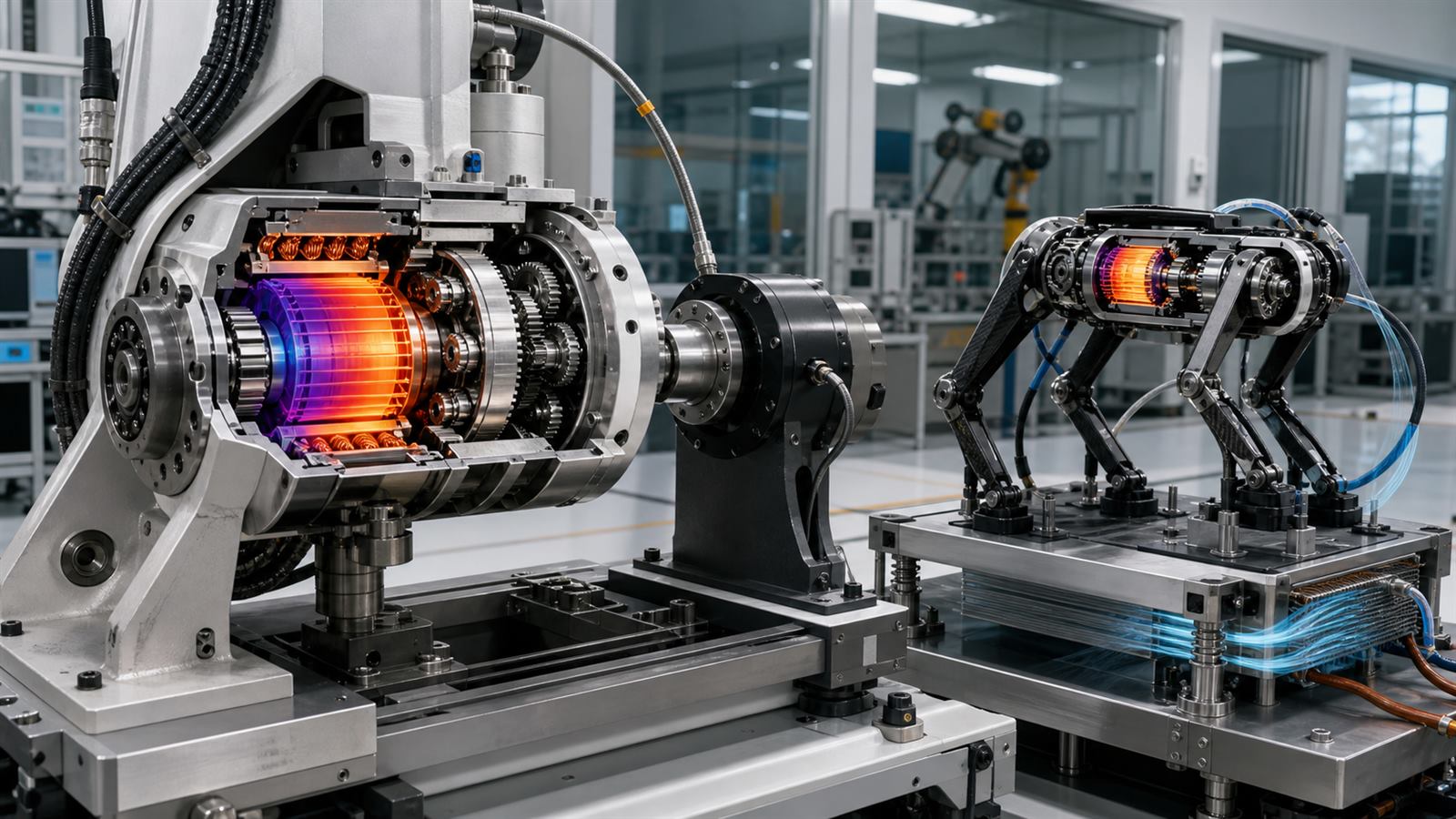
A robot joint specification can make peak torque look like the decisive number. It is easy to compare, sounds powerful, and helps produce an impressive jump or lift in a short demonstration. Yet peak torque says little about how long the joint can sustain a load, how quickly it can move, how much heat it generates, or what happens when the robot collides with the world.
Actuator design is a system tradeoff among the electric motor, gearbox, bearings, sensors, power electronics, cooling, structure, and controller. A useful specification needs to describe that complete joint under a realistic duty cycle. Otherwise, the largest number on the page may represent only a burst that lasts until a thermal limit intervenes.
Peak torque and continuous torque answer different questions
An electric motor produces torque in proportion to current over much of its operating range. More current can create a short burst of force, but resistive heating rises approximately with the square of current. Windings, magnets, insulation, bearings, and electronics all have temperature limits.
Peak torque is therefore a short-duration capability defined by starting temperature, current limit, voltage, cooling, and allowed time. Continuous torque is the level the actuator can maintain once heat generation and heat removal approach equilibrium. Neither number is meaningful without its test conditions.
A peer-reviewed quasi-direct-drive exoskeleton study illustrates the distinction clearly. Its actuator produced a reported nominal torque of 17.5 newton-meters and a peak near 42 newton-meters under different currents, while the researchers separately measured stator and housing temperatures during sustained operation. The result is specific to that design and test, but the measurement method is the important lesson.
A duty cycle turns a burst into an engineering requirement
A humanoid standing still, a quadruped climbing stairs, and a robot arm repeating a pick-and-place motion impose different thermal loads. A joint may deliver high torque for one second, recover during a swing phase, and remain within limits. The same joint could overheat while holding a heavy object at arm’s length.
Engineers therefore use time histories rather than one load point. They examine root-mean-square current, joint speed, regeneration, ambient temperature, airflow, contact with heat-spreading structures, and how neighboring actuators warm one another. A published continuous rating should state the cooling arrangement and temperature criterion, while a peak rating should include duration and recovery time.
This matters especially for humanoid robots expected to work for long shifts. A brief athletic demonstration does not establish repetitive-work endurance.
Gear reduction exchanges speed for torque
A gearbox lets a fast motor produce more output torque at a lower joint speed. Increasing the reduction ratio can make a smaller motor lift a larger load, but it also changes reflected inertia, friction, backlash, efficiency, and how easily external forces move the joint.
High-ratio transmissions suit accurate position control and slow heavy tasks. They can also make contact feel rigid and hide output torque behind uncertain friction. Low-ratio, or quasi-direct-drive, systems use motors with greater torque density and less reduction. They tend to be easier to backdrive and can estimate joint torque more directly from motor current, but the motor and electronics may be larger and thermally demanding.
There is no universally superior ratio. A gripper finger, a warehouse arm, a walking knee, and a mobile robot wheel occupy different regions of the torque-speed map.
Backdrivability changes how a robot handles contact
A backdrivable joint can be moved from its output side with relatively little force. That property lets a leg yield during impact, helps a person guide an arm by hand, and reduces the apparent mechanical impedance presented to the environment. It is not the same as being intrinsically safe, because mass, speed, control faults, sharp tools, and stored energy still matter.
The original MIT Cheetah actuator research treated torque density, efficiency, force-control bandwidth, and impact mitigation as connected design goals. The researchers used low reduction and low leg inertia to improve backdrivability while retaining high-bandwidth control. Their impact-mitigation metric also showed why a transmission cannot be evaluated by static torque alone.
Series elastic actuators take another route by placing a spring in the force path. Spring deflection provides a force measurement and mechanical compliance, but adds travel, resonance, packaging, and control considerations. Software-controlled compliance cannot simply erase the inertia and friction of the hardware beneath it.
Torque density must include the whole joint
Motor torque divided by motor mass can be useful when comparing similar electromagnetic designs. A robot carries more than a motor, however. The gearbox, housing, bearings, encoder, brake, cables, inverter, cooling hardware, and structural interfaces all contribute mass and volume.
Where that mass sits matters. Weight near a robot’s body is easier to accelerate than the same weight near a foot or hand. Designers sometimes use remote motors with belts, tendons, or linkages, accepting complexity to reduce limb inertia.
Our article on robot hands and tactile sensing describes a similar integration problem: adding sensing and dexterity is valuable only if mass, wiring, durability, and calibration remain manageable.
Speed, bandwidth, and torque cannot all peak together
An actuator has a torque-speed envelope, not one operating point. Voltage limits maximum motor speed, current limits torque, and available electrical power constrains combinations of both. Gear losses and motor efficiency vary across the map.
Control bandwidth adds another dimension. A joint may produce large static torque but respond too slowly for stable foot contact or force control. Sensor filtering, communication delay, inverter update rate, structural resonance, and gearbox compliance can all limit the closed-loop response.
A 2024 two-speed robotic actuator study explored one response to conflicting requirements: changing effective gear ratio so the mechanism can support high force in one mode and higher speed with better backdrivability in another. The proof of concept also highlights the extra mechanisms and control needed to shift without losing authority.
Bench tests need wear and repeated impacts
Fresh gears and bearings do not describe lifetime performance. Backlash can grow, lubricant can change, cable strain relief can fail, seals add friction, and repeated shock loads can damage teeth or bearings. Thermal cycling can loosen interfaces and alter sensor offsets.
An open-source legged-actuator study reported electrical, mechanical, thermal, and wear characterization, including hundreds of thousands of gait cycles. The specific design is not a universal benchmark, but publishing the test history makes the result far more useful than a peak specification without endurance evidence.
For precise industrial work, wear also affects calibration. Our comparison of robot accuracy and repeatability explains why a machine can return consistently to the wrong physical location as loads and geometry change.
Power electronics and batteries set system limits
Multiple joints can request peak current simultaneously during a jump, recovery step, or heavy lift. The battery, DC bus, connectors, inverters, and protection system must survive that combined demand. Regenerative braking can return energy, but only when the bus and battery can accept it.
Thermal derating should be coordinated with motion planning. If one knee approaches its limit, the robot may redistribute load, slow the task, change posture, or stop safely. A controller that assumes the advertised peak is always available can generate commands the hardware cannot deliver.
How to read an actuator specification
Look for continuous and peak torque with durations, joint speed at those loads, full actuator mass, gear ratio, backlash, efficiency, reflected inertia, backdrive torque, torque-control bandwidth, sensor method, cooling conditions, ambient temperature, ingress protection, and expected service life.
Then ask for the duty cycle used to validate the joint. A useful report should show temperature over time, electrical power, repeated-cycle performance, impact loads, and any software derating. For a complete robot, check whether ratings apply to one isolated actuator or all joints operating together.
What to watch next
Better magnetic materials, winding methods, power semiconductors, compact cooling, integrated torque sensing, variable transmissions, and co-design software will keep improving robot joints. The more important market change will be standardized reporting that makes sustained work, contact behavior, and durability comparable across machines.
Peak torque will remain useful, but it should be the start of a question rather than the end of one. Robots become practical when their actuators deliver the required force, speed, compliance, and uptime together.
Leave a Reply